
By Ed Malaker
Posted 12/16/2020
Recently, we covered how to wire a Fender Stratocaster from scratch, to create a pre-wired harness. In this article, we’ll explain how to do the same thing, with the aid of a Telecaster wiring diagram. If you own a Fender Telecaster, this guide can be useful in solving a number of problems, such as rewiring your guitar from scratch and creating pre-wired harnesses for sale.
Getting Started with a Stock Telecaster Wiring
The Stratocaster guide is a little easier because all electronics, except for the output jack, are attached to the pickguard. In the Telecaster, one pickup is under the pickguard, one is attached to the body by the bridge, and the remaining electronics are connected to the control plate that houses the tone control, volume control, and three-way switch. The output jack is on the body.
Tools and Materials Needed
- Fender Telecaster Neck Pickup
- Fender Telecaster Bridge Pickup
- Two 250k potentiometers
- One .047uf capacitor
- One three-way pickup selector switch
- One output jack
- Soldering iron
- Solder
- Screwdriver
- Pliers
- Wire
Installing and Uninstalling the Neck Pickup
To install or uninstall the neck pickup on most Telecasters, you need to remove the pickguard to access the screws that hold it in place. With the pickguard removed, you can uninstall the pickup by removing the two screws and carefully pull the pickup wires through the wire canal once you disconnect them from the control panel.
To install the neck pickup, reverse the process. First, carefully feed the wire through the wire cavity to the control panel, then fasten the pickup to the body of the guitar using the two installation screws. Once installed, replace the pickguard.
Installing and Uninstalling the Bridge Pickup
To install or uninstall your bridge pickup, you will need to remove the bridge plate. The bridge plate can have up to eight screws holding it in place, and it houses the bridge pickup and string saddles. Once you remove the bridge plate, you can unscrew the pickup and remove it. Disconnect the wires in the control panel and gently pull them through the wire cavity.
Again, installing the pickup will use the opposite approach. Feed the wire through the wire cavity to the control panel, then screw the pickup to the bridge plate before reinstalling it.
The Control Panel
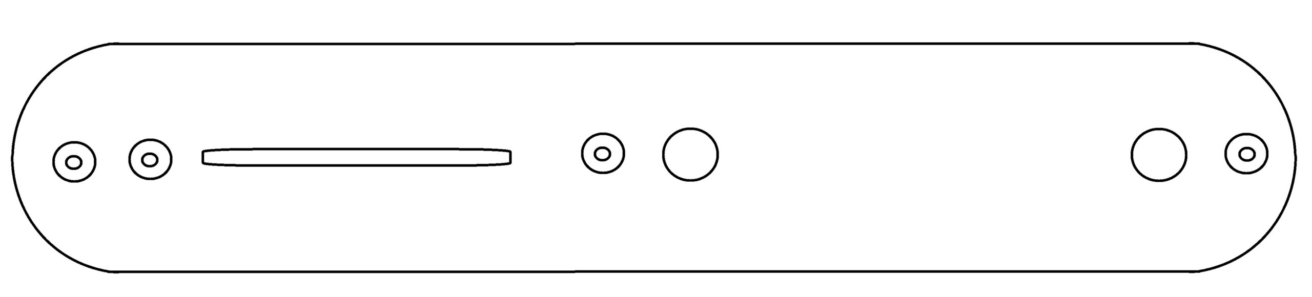
With the pickups in place, we can begin to work on the control panel, which is the heart of the guitar. The control panel has a long, usually metal cover that looks like the illustration in Example 1.
Example 1
Installing the Components
Much like the bridge plate, the metal cover serves a specific purpose, so if you’re going to use a non-metal cover, you will need to coat the inside with a conductive tape or paint. The control panel houses the switch, volume control, and tone control. We need to attach all components to the component cover, so we’ll do that first.
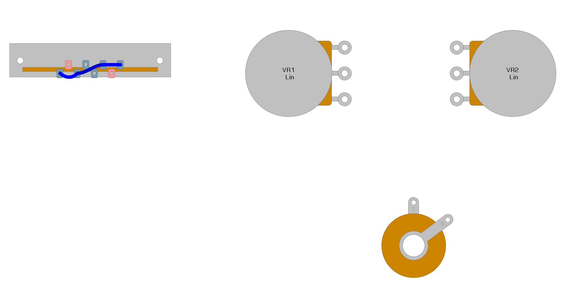
We’ll set up our wiring diagram to mimic the positions of each component on the control panel cover. We illustrate this in Example 2 as we begin our stock Telecaster wiring diagram.
Example 2

The three-way switch is attached to the control panel cover by two screws.
The volume control and tone control are identical, usually 250k pots.
Beginning the Stock Telecaster Wiring
In this section, we’re going to discuss the steps you need to take to wire the control panel.
Step 1: Wire the Switch
We’ll start with the switch and connect some of the tabs using short pieces of wire. We demonstrate this in Example 3 using blue wires.
Example 3
Step 2: Connect the Tone to the Volume
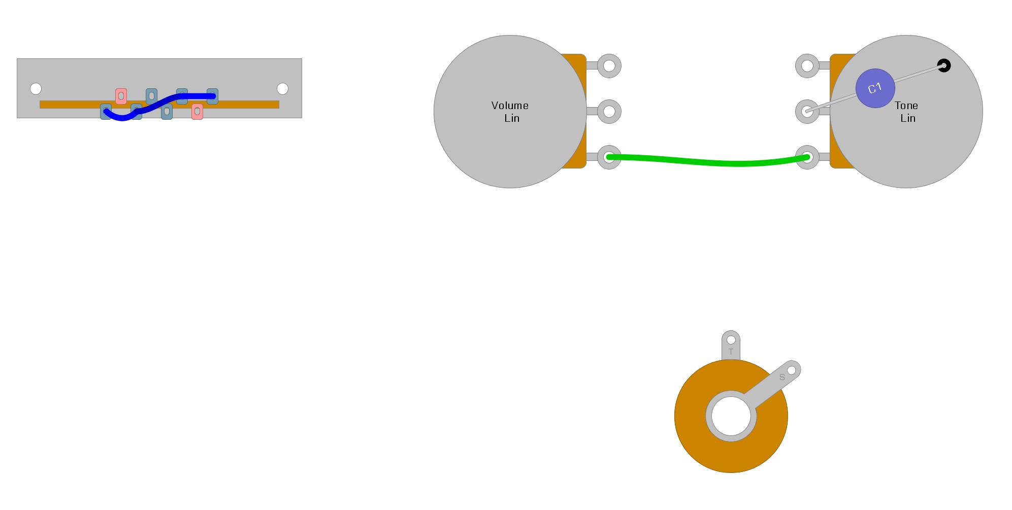
Next, we’ll add the tone control circuit and attach it to the volume control. The standard value for the tone control capacitor is .047uf. If you feel this results in a tone that’s too muddy, you can use a smaller value (down to .011uf) to brighten up the sound when the tone control is engaged.
Using green wire, Example 4 shows where to place the capacitor and how to connect the two pots.
Example 4
Step 3: Connect the Switch to the Pots
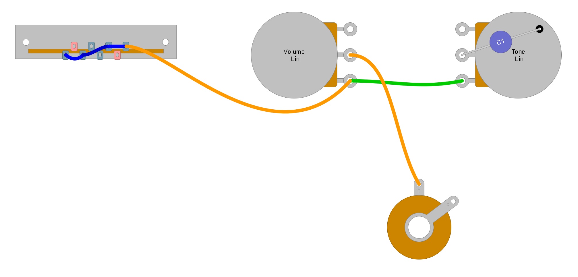
The next step is to connect the switch to the volume control, and while we are at it, we’ll connect the volume control to the output jack. We demonstrate this using orange wires in Example 5.
Example 5
Step 4: Connect the Ground wires
Now we’ll need to install the Ground wires. Since some of them go to the pickups, we’ll add them to our diagram as well. In Example 6, the Ground wires are black while the pickup wires are yellow.
Example 6

Finishing Up
Once you’ve connected the Ground wires and attached the pickups, you can install the control cavity cover and output jack. Finally, you can play your guitar!
It may not seem like it from looking at this diagram, but you can prewire your control cavity cover with plenty of modifications to produce new tones. Of course, prewired covers are also available online, offering the Tele player an easier approach to upgrading a guitar. Many harnesses also include new pickups as well.
Conclusion
We hope you’ve found this guide for creating a pre-wired Tele harness helpful. If you’ve learned something new and think it could help others, please feel free to share this article on Facebook and Twitter. For more articles on guitar electronics, visit humbuckersoup.com.


