By Ed Malaker
Posted 04/17/2019
If you are a guitar player looking to create your own unique sound, one of the best ways to do this is to build your own equipment from scratch. A good portion of “Guitar Electronics” is just very simple circuits that can be built and modified at home. In Gain Boost Part 2, we are going to show you how to build a gain boost pedal starting from a kit. The name of the pedal is the Pile Driver, and you can get it here:
ModKitsDIY https://www.modkitsdiy.com/pedal/piledriver
Once we build the pedal, I’ll show you how you can improve the design by adding a power supply jack, an on/off LED indicator, and tone controls. You will also understand how you can include the circuit in your own, more complex projects.
Clean Gain Boost may not top every guitar player’s most wanted effects list, but it is a vital one that is used everywhere, so understanding it is important. Some effects pedals use multiple gain stages to create overdrive, or to run stereo outputs. Any type of buffered bypass is also a gain circuit, as well as any preamps. Active pickups, and many acoustic guitar pickups also use a gain circuit in their design.
Gain Boost Part 2: Getting Started
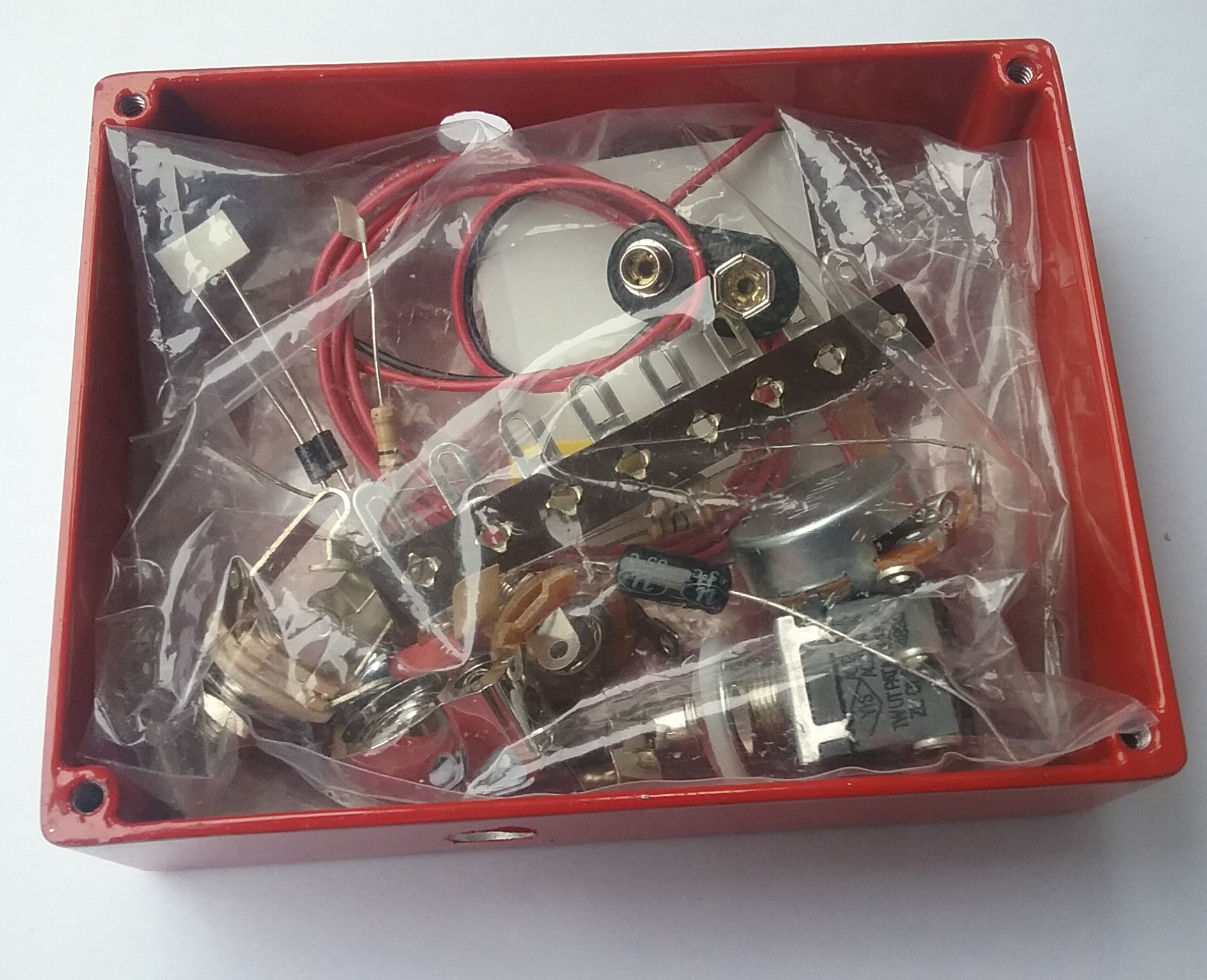
In Guitar Gain Boost Part 1, we went over all the parts that came in the Pile Driver kit, which we will be using to build our gain boost pedal. In this article we are just going to dive right in and get started building.
This is a very simple project to build, and we will be breaking down each of the already easy-to-follow steps into even easier-to-follow steps.
SECTION 1 – Terminal Components
Step 1
We start with the empty Terminal Strip that looks very much like Figure 1.
Fig 1
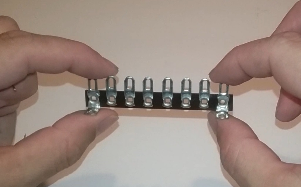
The Terminal Strip is a strip of non-conducting material on which, in this model, eight metal posts are attached. We will solder all the components for our project to these metal posts.
Terminal Strips are great for beginner and small projects. In a future article, we will show you how to put this same project into a standard PC board. Creating this circuit in a PC board will make it a lot smaller and allow you to use it in other projects.
The first thing that you want to do is hold the post board like it is in Figure 1 and mentally number the posts from 1 to 8, going from left to right.
Step 2
Next, solder the two diodes to the Terminal Strip. Each of the diodes has a Grey/Silver polarity strip at one end, and it’s important to solder them in the correct direction.
The first diode goes from post 1 to post 3, with the Grey polarity strip at post 3.
The second diode goes from post 3 to post 5, with the Grey polarity strip at post 5.
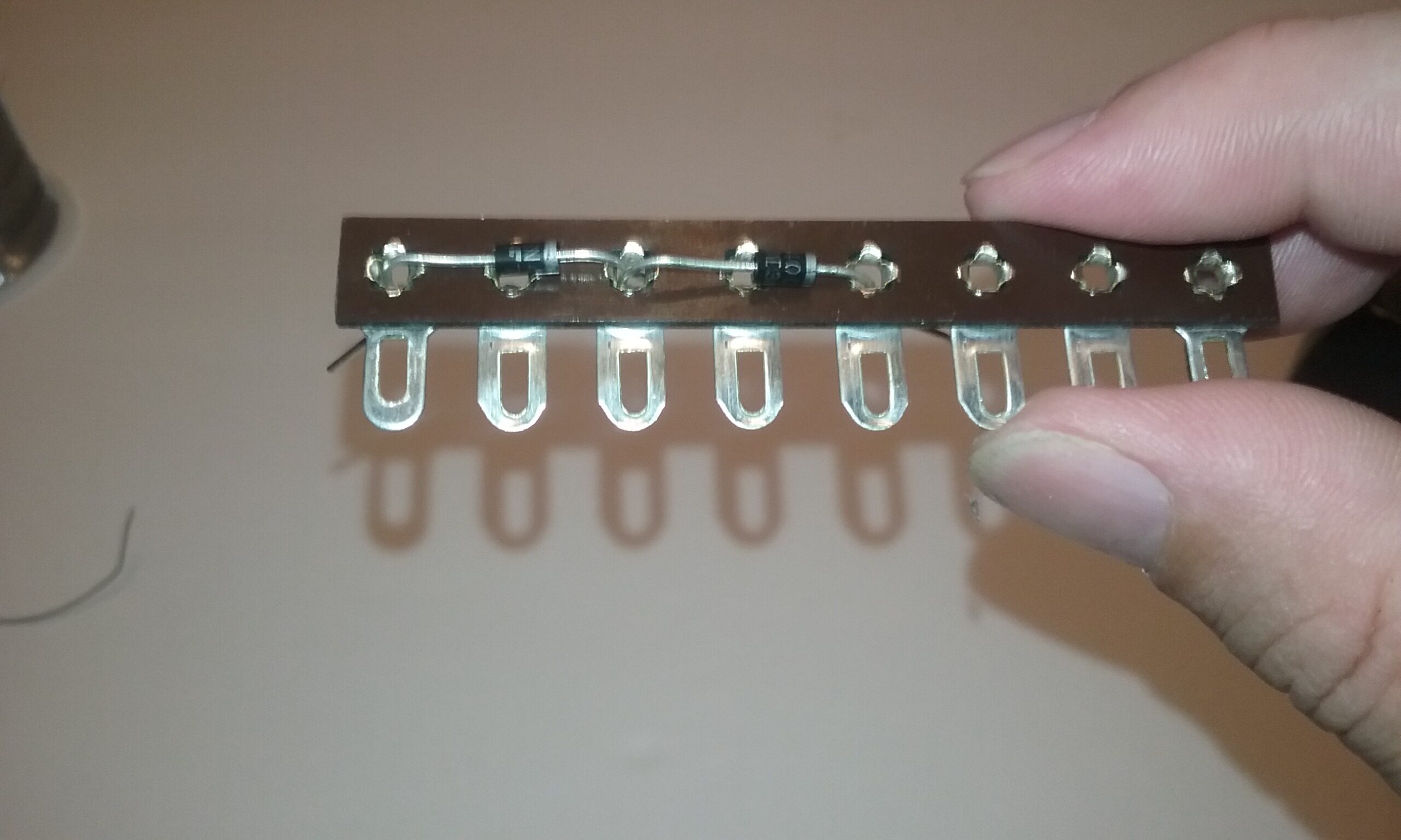
The directions tell us to place the diodes, but not to solder them until after the next step. When you are finished, it should look something like Figure 2.
Fig 2
Step 3
According to the directions, the next thing is to add the capacitor to post 3 and solder everything to the terminal strip.
This is a large yellow capacitor, and we do not need to worry about polarity. We only solder one end of the capacitor to the post; we leave the other end unconnected for now. We won’t be attaching the other end of the capacitor until we attach the Terminal Strip to the metal box. When you’re finished it should look like Figure 3.
Fig 3

Step 4
Per the directions, we next want to add the transistor. The transistor is the most sensitive component in this project, so be sure to use extra care when inserting and soldering the component.
Legs on a transistor are easily broken, and it is also easily damaged by static electricity. Transistors are also melted quite easily by a soldering gun that’s too hot.
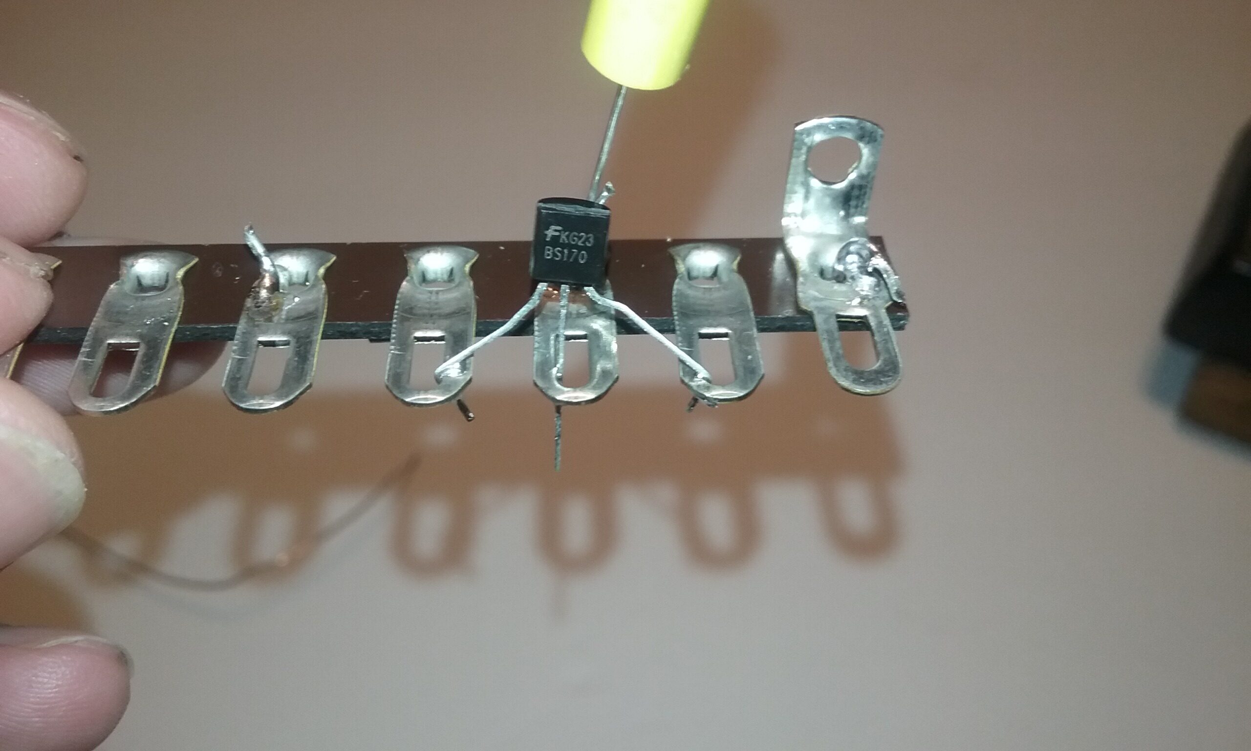
The three legs will have to be soldered to posts 2, 3, and 4, exactly the way that they are shown in Figure 4.
Fig 4
Step 5
The next step is to mount a 1M resistor to posts one and three, as shown in Figure 5. Resistors can be placed in either direction.
Fig 5

Step 6
Then we add another 1M resistor to posts 3 and 4, as shown in Figure 6.
Fig 6
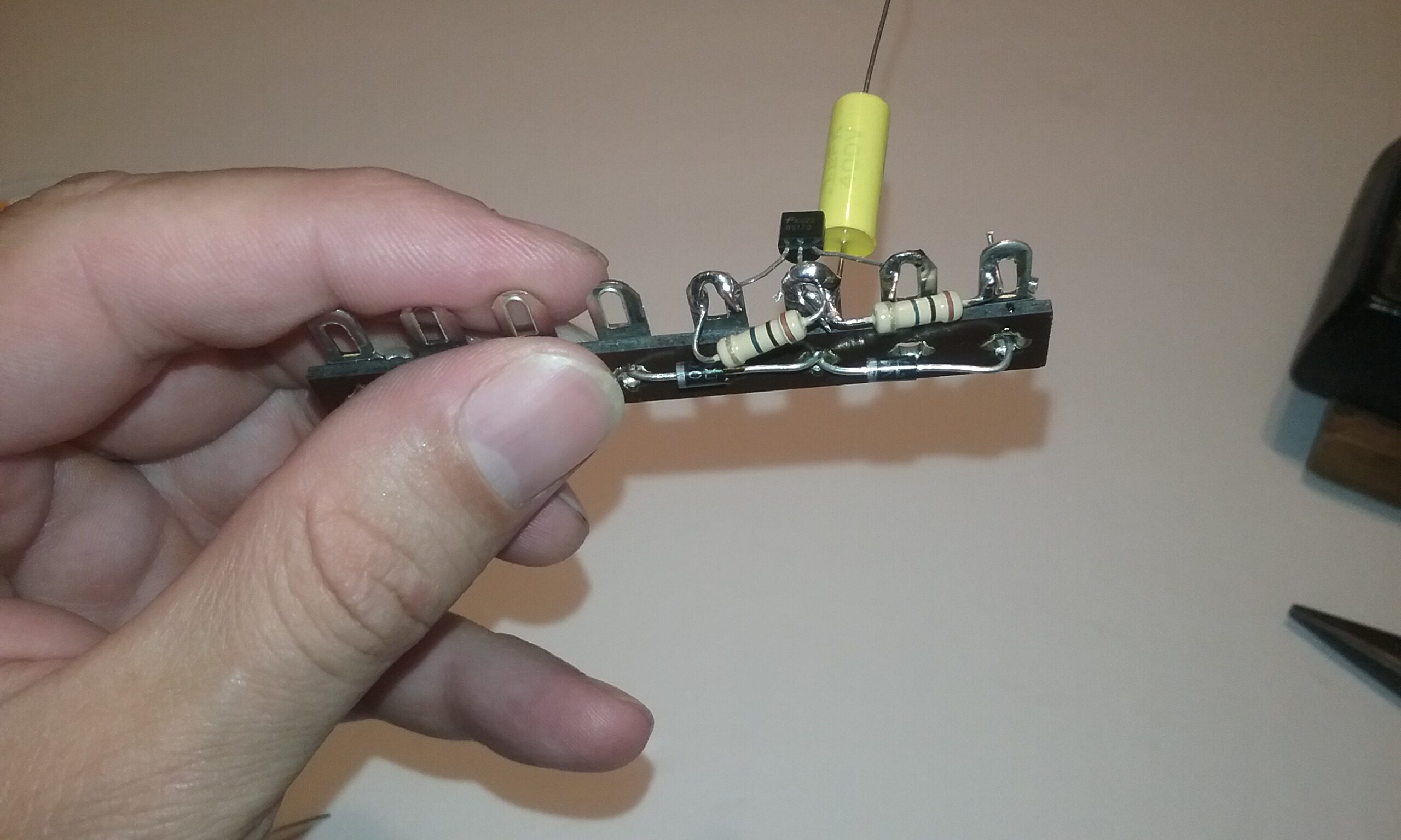
Step 7
Next, the directions tell us to add a 5.1K resistor to posts 5 and 6, as shown in Figure 7.
Fig 7

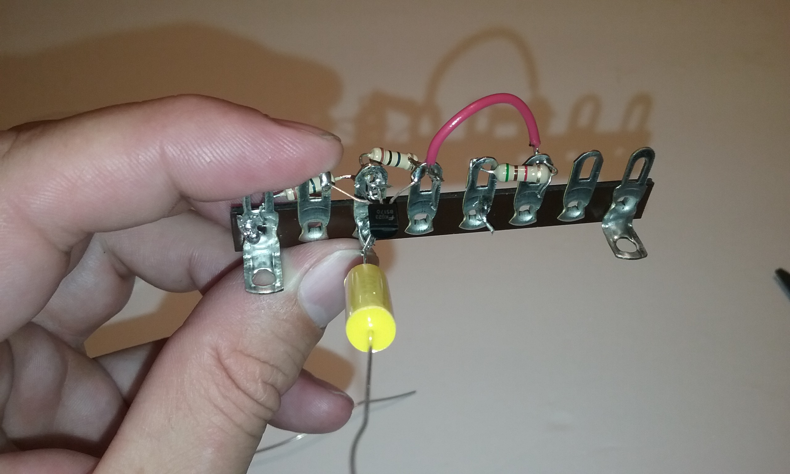
Step 8
The next step is to add a short piece of wire that connects posts 4 and 6, as seen in Figure 8.
Fig 8
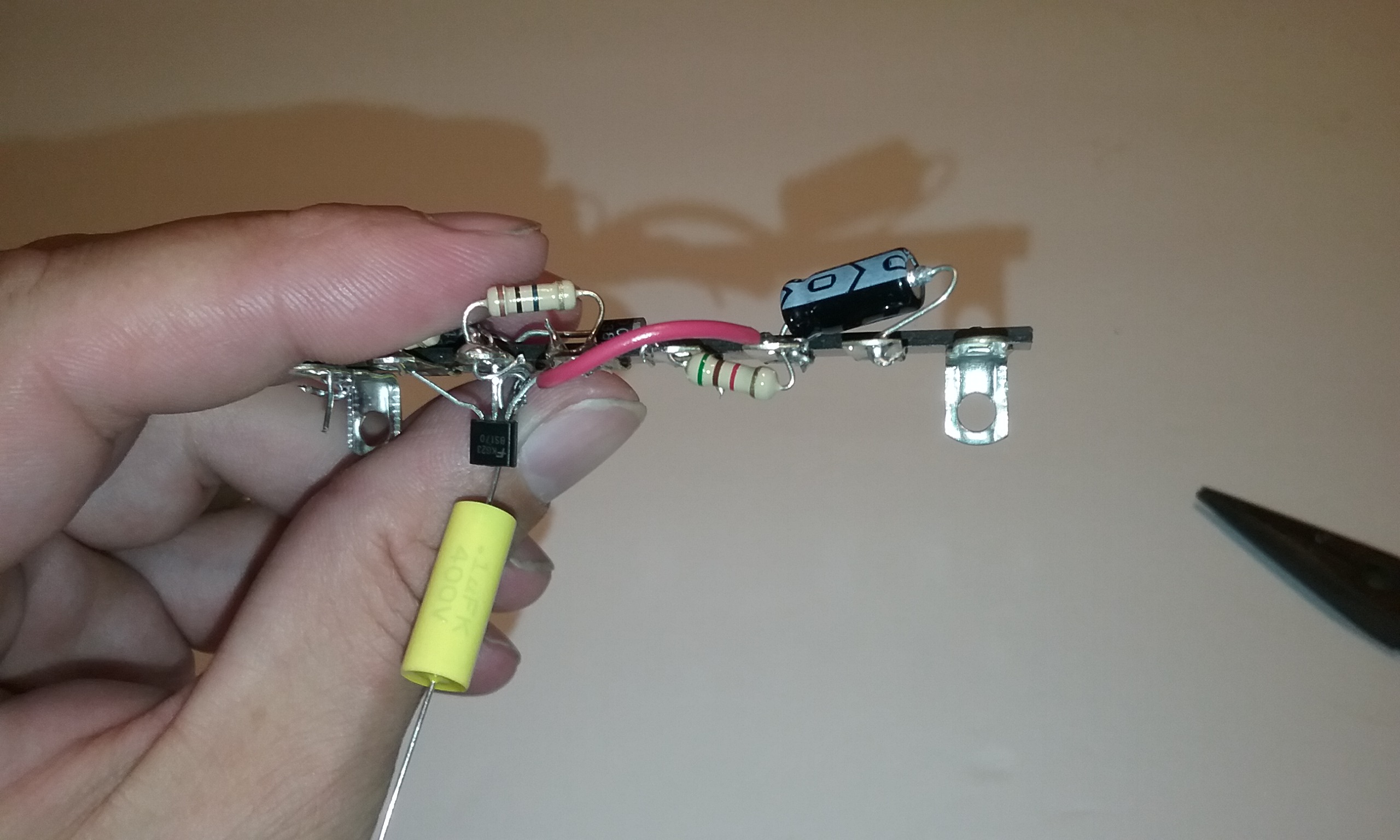
Step 9
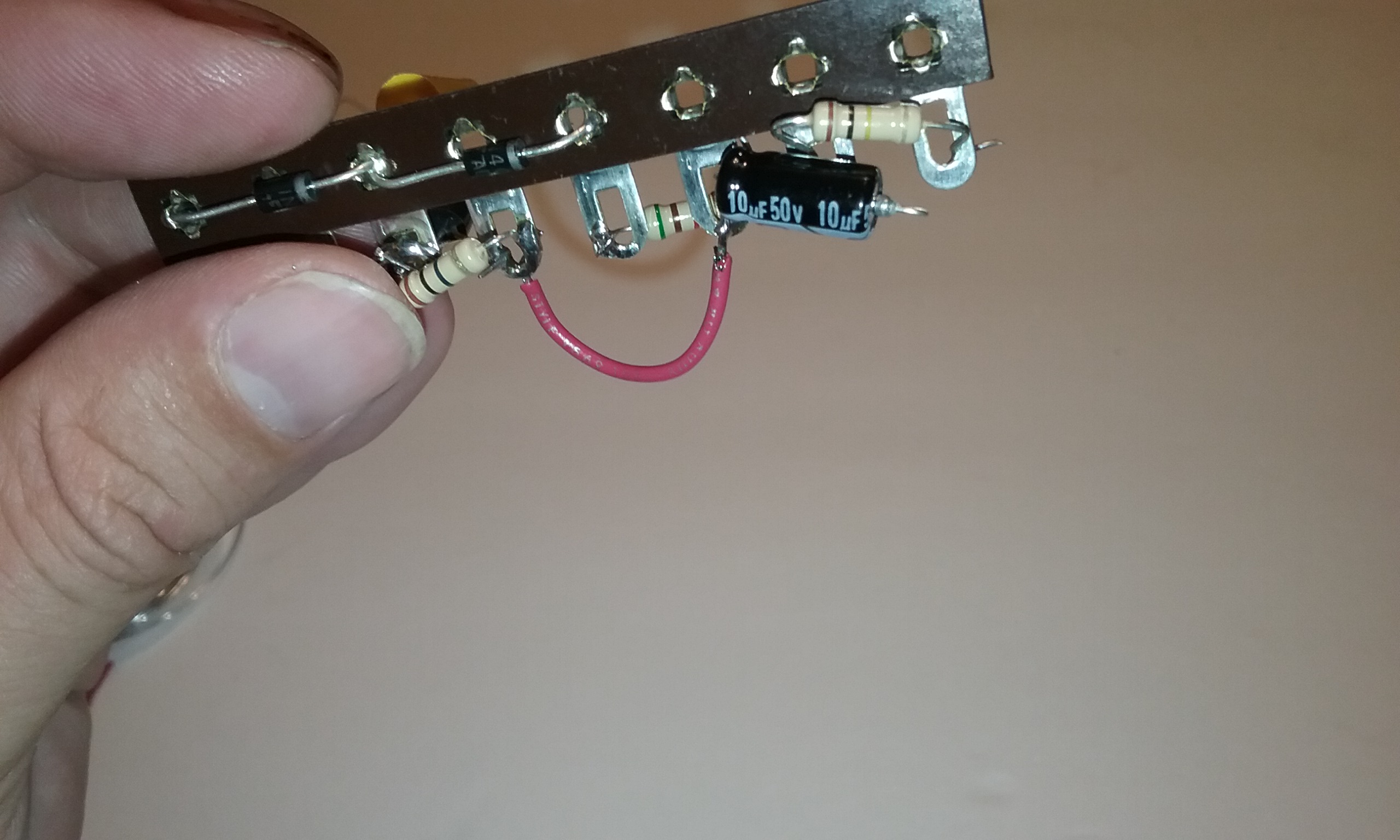
The next thing that we need to do is add the 10uf capacitor. This capacitor has a Grey stripe on it, and we connect the terminal closest to that Grey stripe to post 6. We connect the other terminal to post 7. When you are finished, it should look like Figure 9.
Fig 9
Step 10
The final thing that we need to do in this section is add the 100K resistor to posts 7 and 8. Once you do this, it should look like Figure 10.
Fig 10
Summary
That brings an end to the Terminal Strip components section of Gain Boost Part 2. In the next article of this series, we will place this terminal strip into its metal enclosure, hook up the input and output jacks, and hook up the volume control, and the battery connector. Finally, we will test it out and see if it works. Looking forward to seeing you there!
If you’ve found this article helpful, please feel free to share this with your friends on Facebook and Twitter. For more articles on guitar electronics, visit humbuckersoup.com.