By Ed Malaker
Posted 12/28/2018
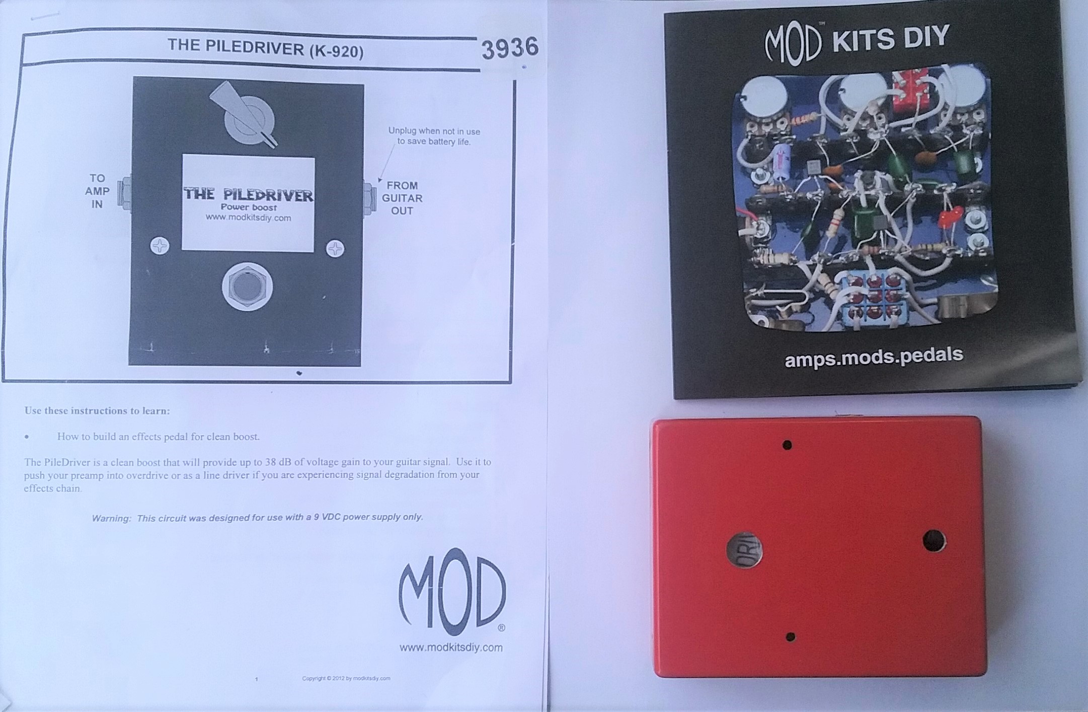
In Part 1, we’ll take a look at the first actual pedal that we are going to create. It’s called the Piledriver, and it is a Gain Boost pedal that I got from modkitsdiy.com (https://www.modkitsdiy.com/pedal/piledriver). This is listed as a “beginner” pedal and that is one of the reasons that I chose it. Gain Boost is also one of the most common processes that take place in every pedal, and understanding it will put you well on the road to building great-sounding pedals.
We purchased the Piledriver Kit through Amazon because I use them often, so I cannot comment about modkitsdiy.com in reference to shipping.
When the package arrived all of the parts listed in the manual were present and everything looked to be in good shape.
NON-TESTABLE PARTS
Figure 1
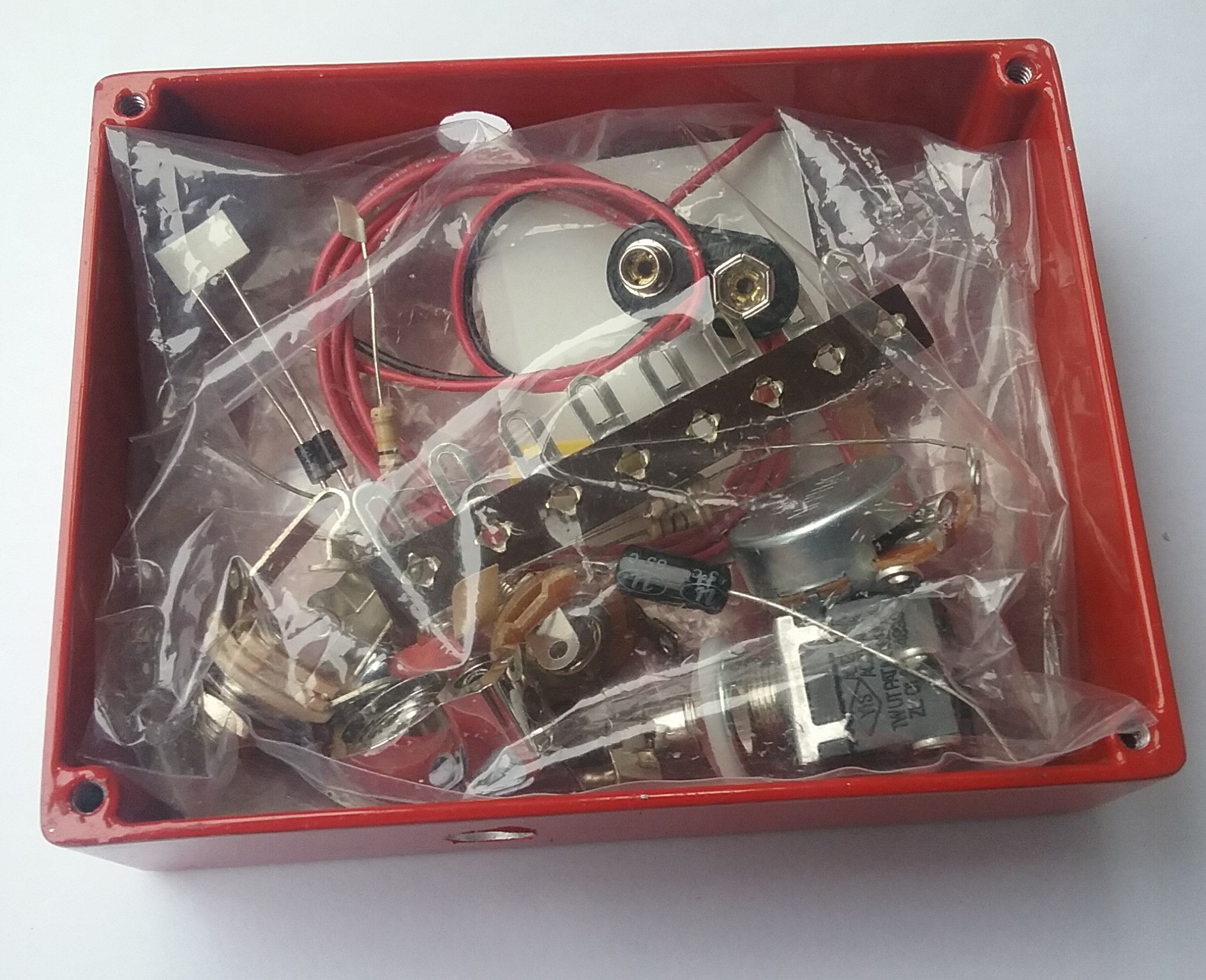
There are only a few electronic parts in this kit, some screws, some wire, and the box itself. All of the components were neatly, and very securely, packaged inside the foot pedal box.
Figure 2
Let’s take a look at each of the parts and I will try to explain a little about each of them.
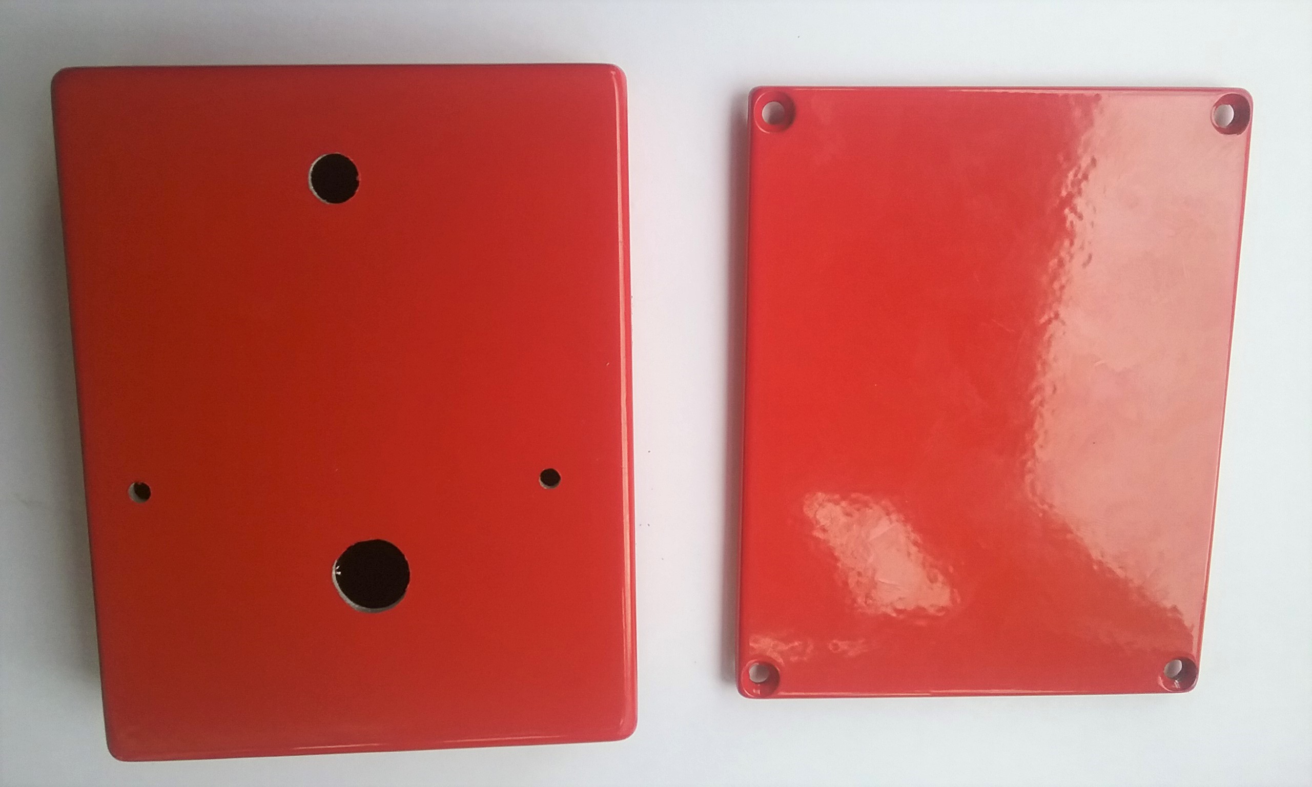
1 – The Box – The pedal box itself is a sturdy case that’s painted a Deep Red, and it seems like a good, high-quality finish. The box is smaller but MUCH more sturdy than I was expecting, judging from the images on the internet. I would not have been surprised if this piece was of lesser quality.
Figure 3a
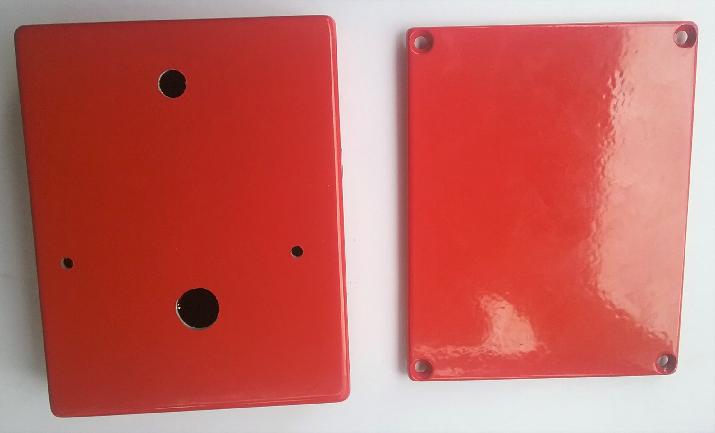
Figure 3b
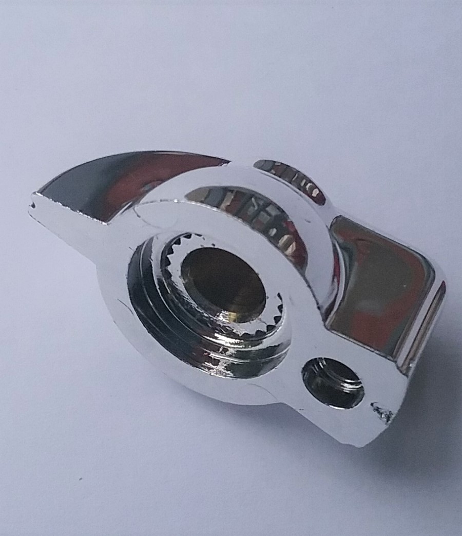
1 – Chicken Head Knob – A hard chrome-plated plastic (I think); it feels and looks like good quality. I would not have been surprised if this piece was of lesser quality.
Figure 4a
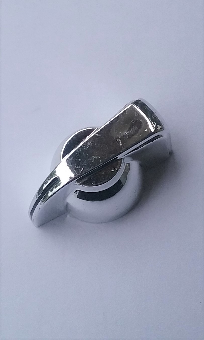
Figure 4b
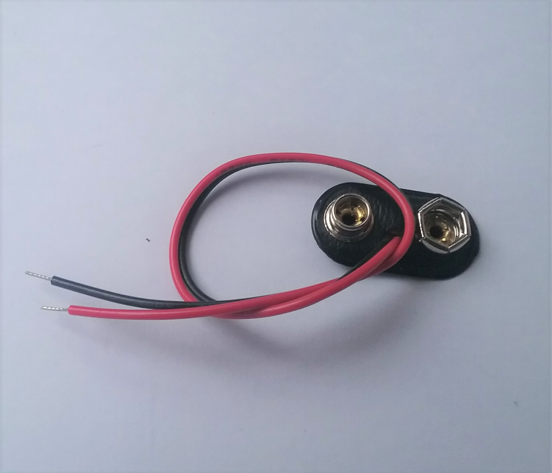
1 – Battery Clip – This is a simple component and is similar to a pack of cheap spares that I keep handy for emergencies. There are much higher-quality clips available but it is about what I was expecting from a beginner kit.
Figure 5a
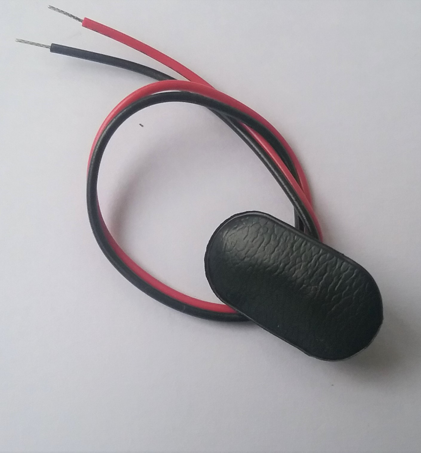
Figure 5b
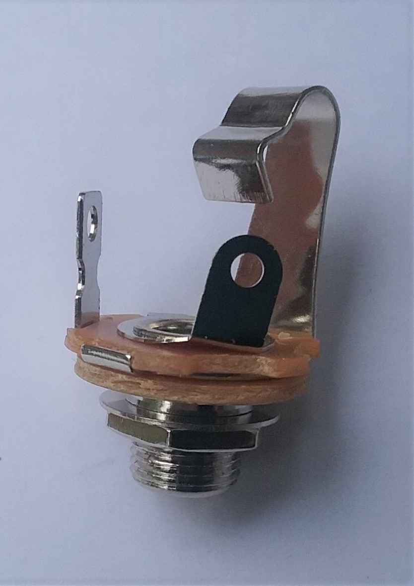
1 – 1/4 Mono Jack – This is a standard guitar jack that seems to be of good quality with solid construction.
Figure 6
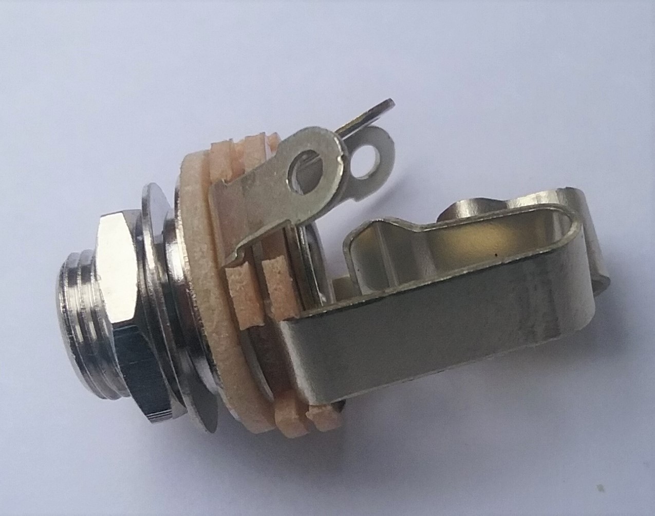
1 – 1/4 Stereo Jack – I was surprised to see a stereo jack in this kit. This jack seems to be of good quality with solid construction.
Figure 7
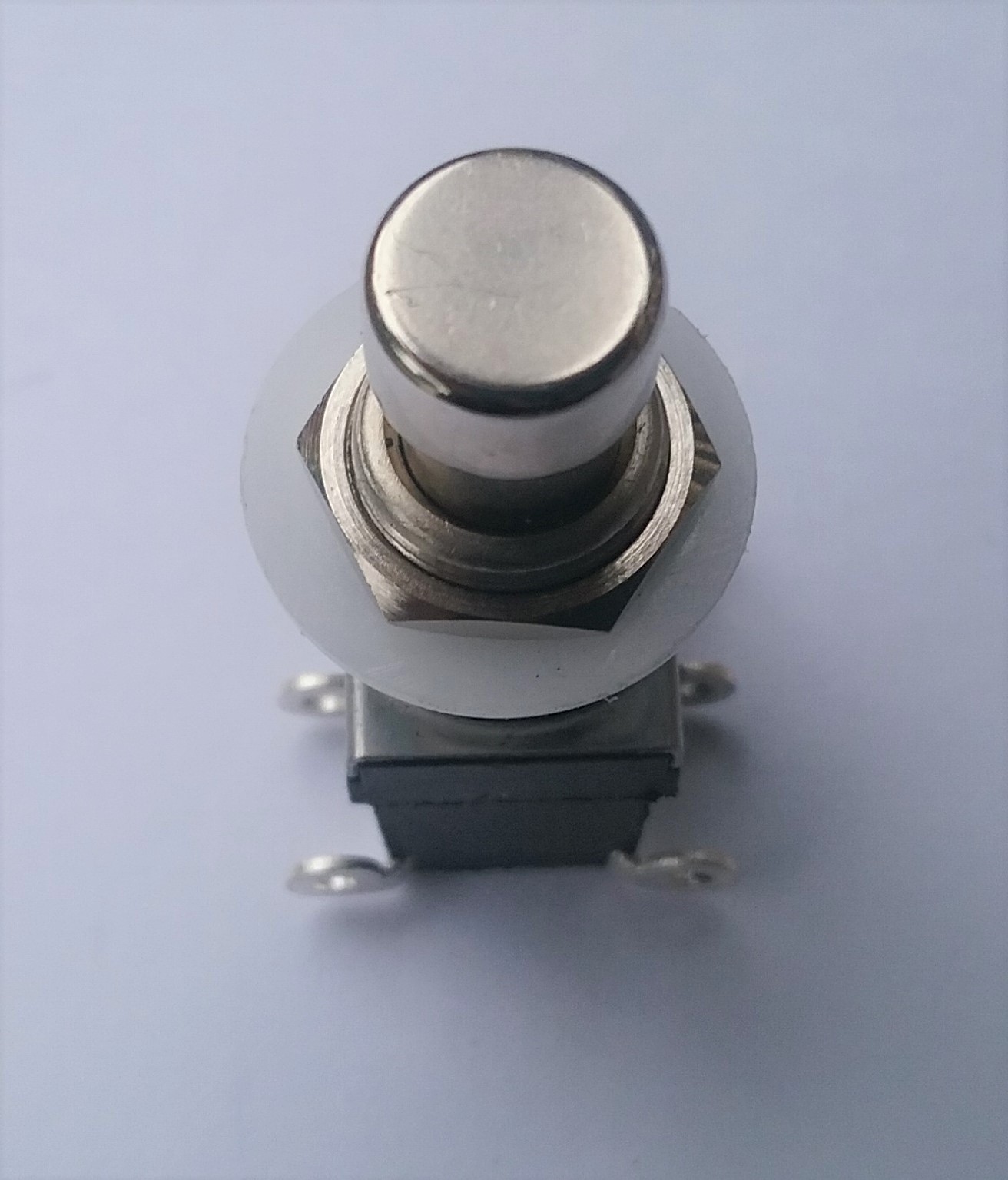
1 – DPDT Foot Switch – The footswitch is a RoHs and it feels like a good quality.
Figure 8a
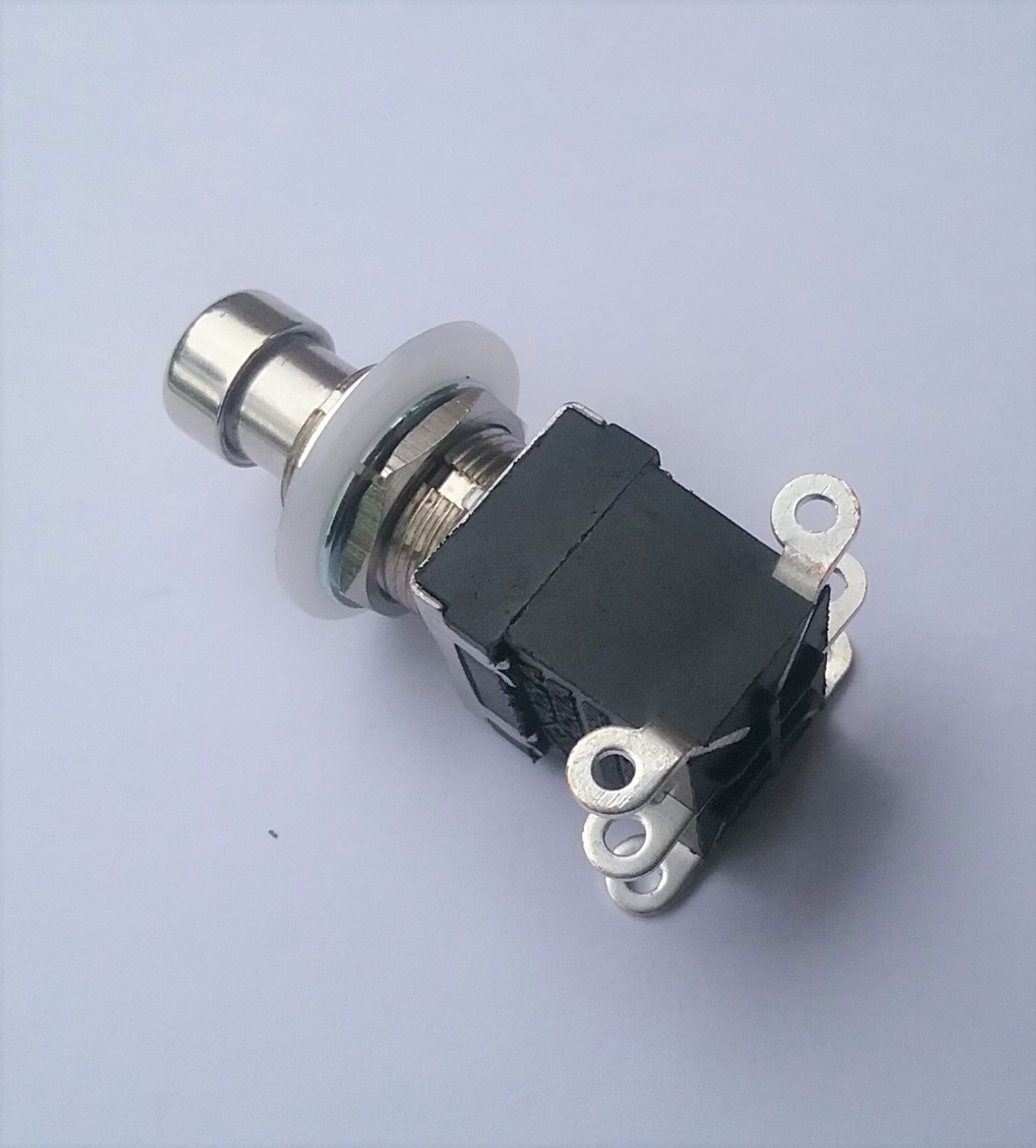
Figure 8b
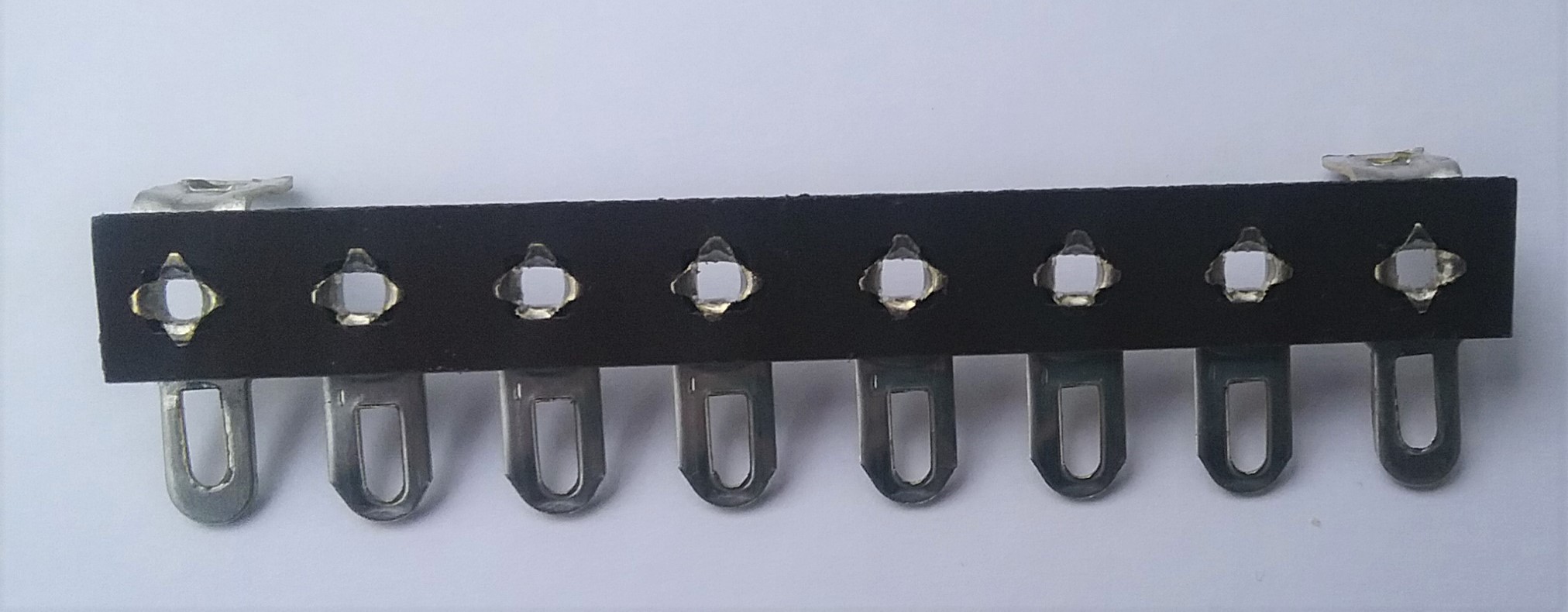
1 – 8 Terminal Strip – This is where you solder the individual components to build your circuit. This is a great way to build test circuits quickly, but it is not the best way to permanently wire an effects pedal. A good MOD that we can do once the project is complete is to rewire the circuit into a circuit board.
Figure 9a
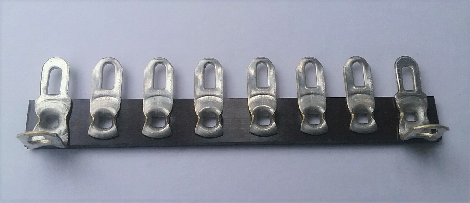
Figure 9b
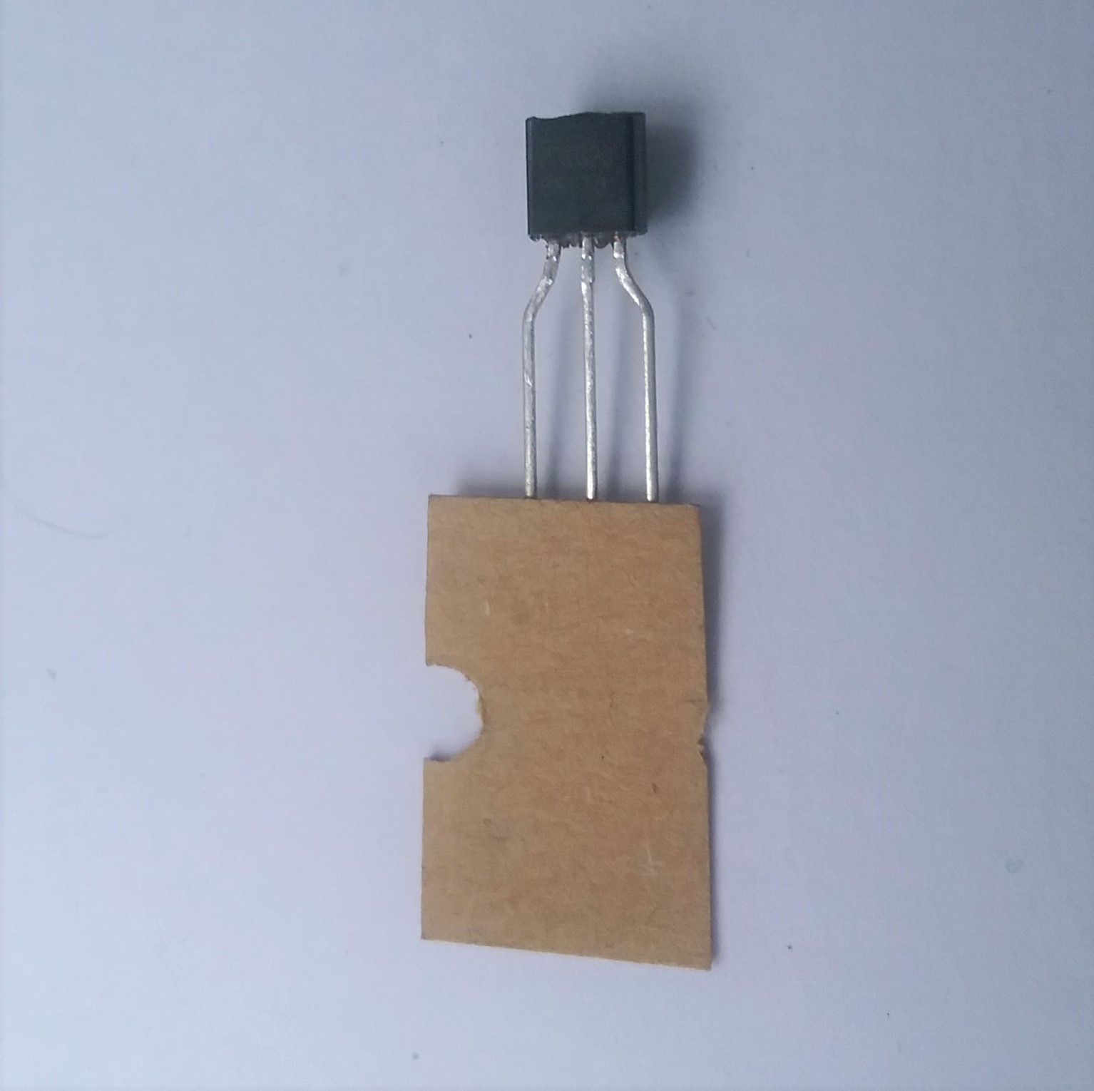
1 – BS170 MOSFET transistor – This is the heart of the Gain Boost and it is also the most easily damaged. A 2N7000 or 2N7002 can be substituted for the BS170 if you “flip” it when you wire it in the circuit. You can also use a MTD3055EL Transistor. A good MOD that we can do once the project is complete is to add a switch to toggle between transistors.
Figure 10
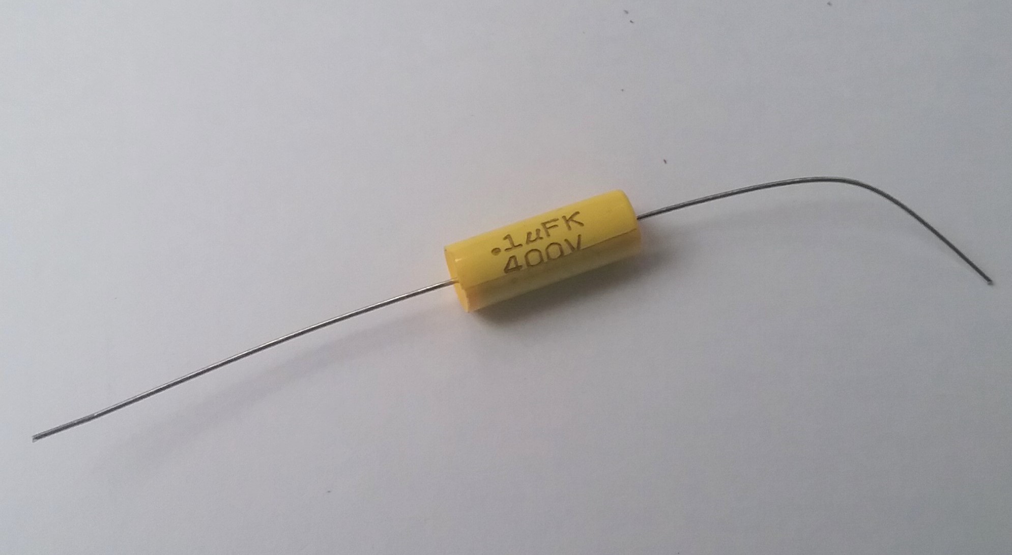
1 – 0.1 uf Capacitor – This is a 400-volt capacitor, that seems kind of extreme but we will see once we build it. I cannot test the value, but based on the quality of the resistors I would say that it’s within 5%.
Figure 11
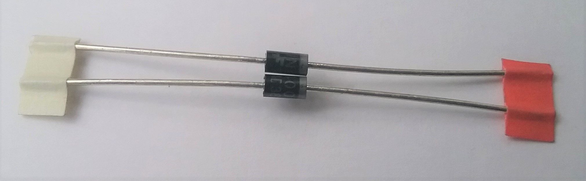
2 – P-Q1N4005 Diode – Once again I have no way to test this component, but based on the resistors I believe that they are a usable quality.
Figure 12a
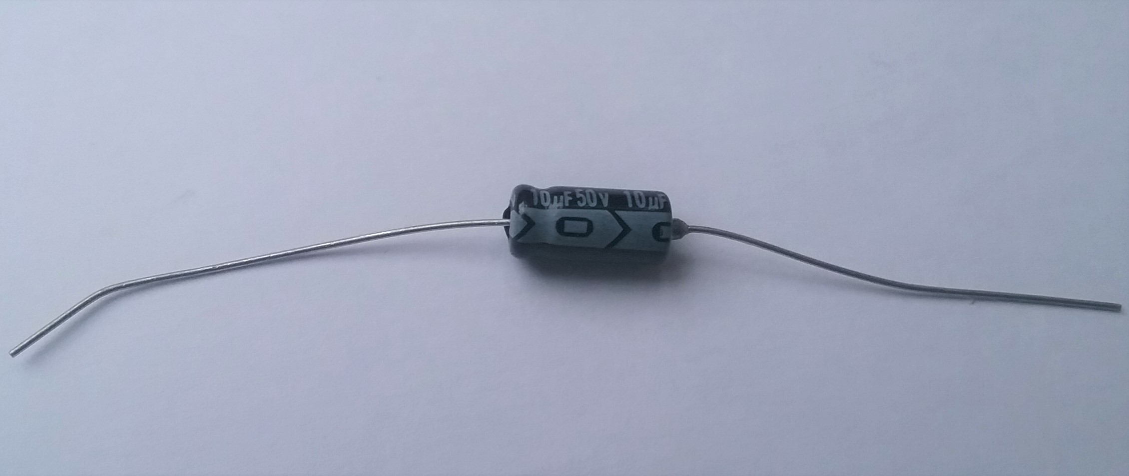
1 – 10uf Polarized Capacitor 50v – A capacitor that looks like many that I have seen before so I assume it is of usable quality.
Figure 13
TESTABLE PARTS
These are the parts of the kit that are testable with our Voltmeter. The values listed on the left are the values listed in the manual, and they are the values that we are aiming for. The values listed on the right are the ones that came in my kit. Your values WILL be different, and you will need to test all of the resistors and the pot yourself.
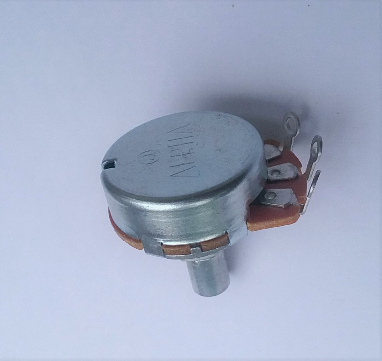
1 – 5k Pot linear R-VA5KL – ACTUAL VALUE 5.3K – EXCEEDS 5% TOLERANCE! If this were a static resistor I would have to take it out and use a different pot but since it is a variable resistor, and the value is too high, we can get the desired value by backing off on the pot. We will see what happens when we test the finished circuit. That the pot is outside 5% could also be an early sign of poor quality with this component.
Figure 14a
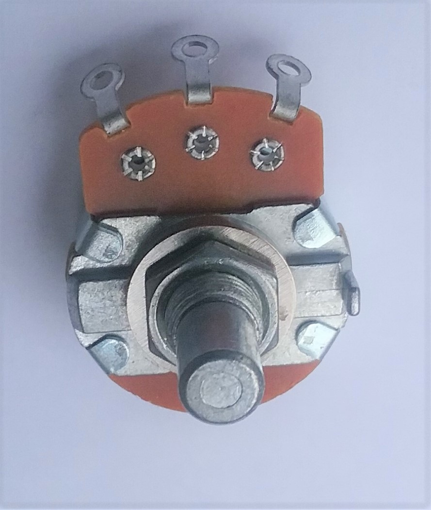
Figure 14b
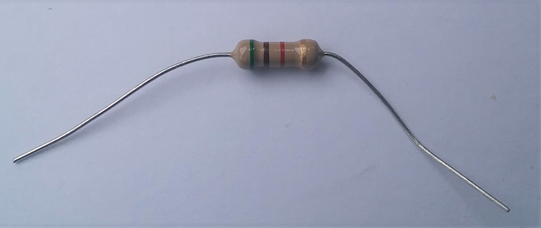
1 – 5.1K Resistor – ACTUAL VALUE 5K
Figure 15
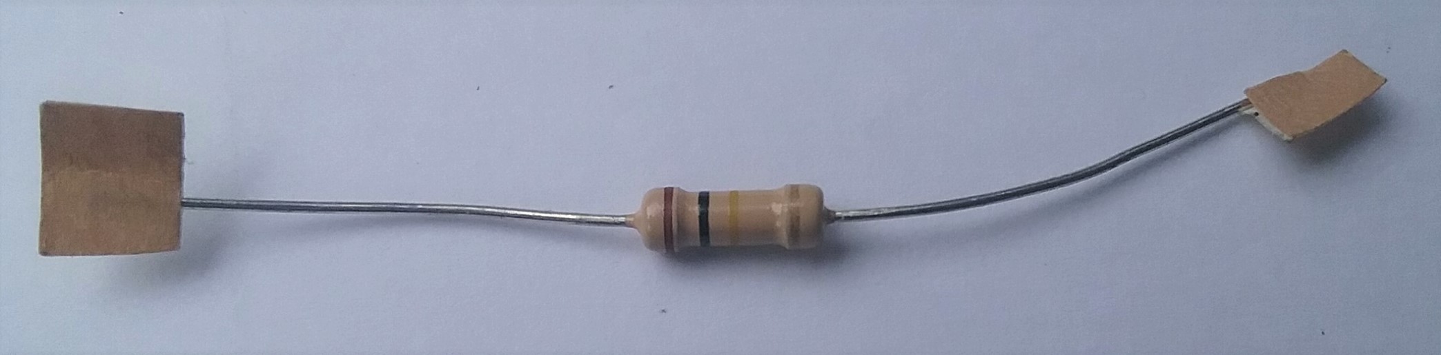
1 – 100k Resistor – ACTUAL VALUE 98.7K
Figure 16
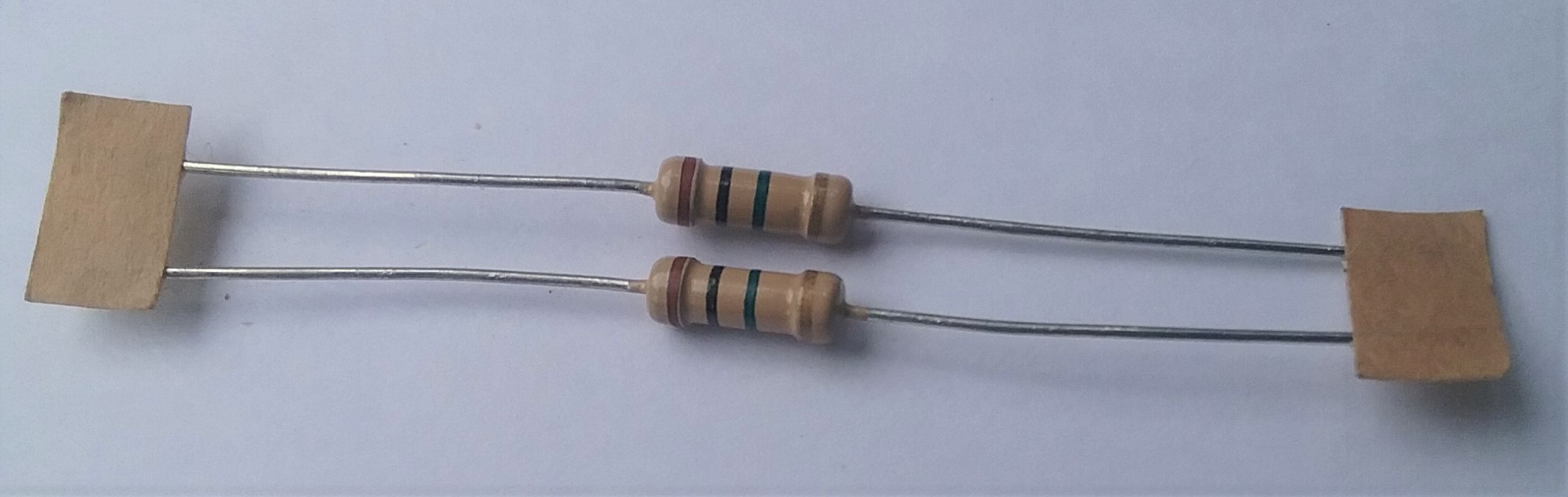
1 – 1m Resistor – ACTUAL VALUE 982K
1 – 1m Resistor – ACTUAL VALUE 981K
Figure 17
The only testable component that tested outside the 5% range was the 5K Pot; the rest of the components are within 3%. It’s likely that all of the components are of similar quality. Not too bad at all for a “Beginners” Kit.
Overall, I would say that the Piledriver Kit looks like a good deal right out of the box, without touching anything. If you built our Test Tone Generator in an earlier article, then you know how to order parts and might want to order some resistors to make up any values you are short on, depending on how worried you are about building a high-quality pedal.
In the next article, we will see if there are any hidden surprises as we put the kit together. I hope to see you there.
If you’ve found this article helpful, please feel free to share this with your friends on Facebook and Twitter. For more articles on guitar electronics, visit humbuckersoup.com.