By Ed Malaker
Posted 09/07/2019
In this post, we’ll show you Seymour Duncan Pearly Gates wiring for your guitar, with the hope that you’ll enjoy the new sound possibilities.
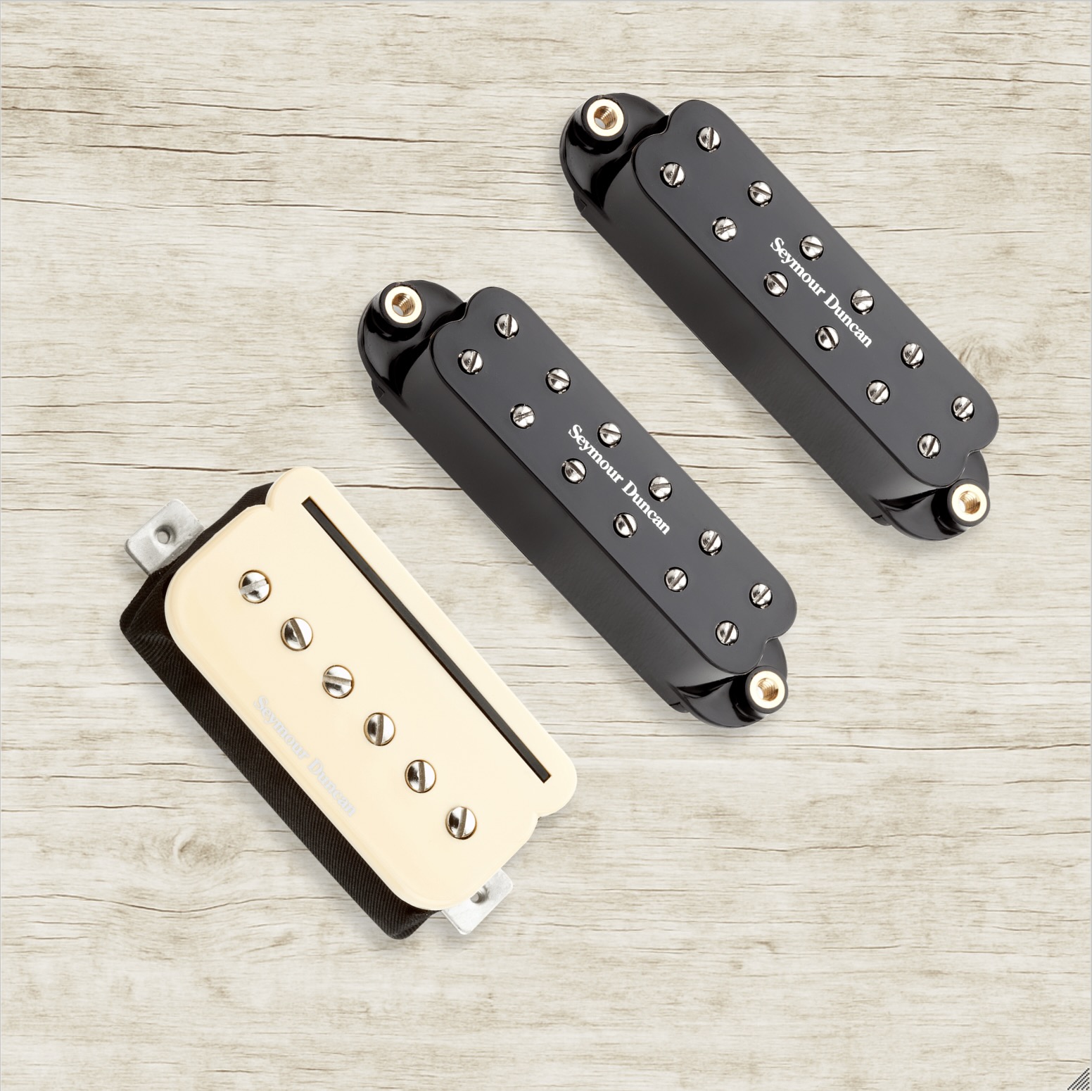
The Pearly Gates is a humbucker that was designed to replicate the sound of a 1959 Gibson Les Paul Standard, which used the legendary P.A.F. pickups. Each Pearly Gates pickup is handmade and wax potted to help reduce feedback. Each also features an Alnico 2 bar magnet and a nickel silver bottom plate, and is installed using four colored conductor wires and a bare wire.
The Wires
The four colored wires are called “conductors” or “leads” because each one carries a small electric current to and from the two coils in the humbucker. Each coil has a positive and a negative wire, and the color that goes to each is called the pickup’s “Wiring Code.” The color of the conductor wires can vary dramatically between manufacturers and sometimes between different. models of the same brand
The Bare wire is the Shield. Its primary purpose is to trap radio frequencies that reach the pickup and shuttle them to ground before they interfere with your sound. The Shield and the coils are not connected, but the Shield does connect to Ground, to remove the interference.
The Wiring Code
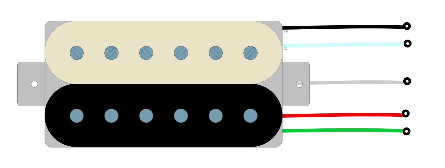
The Seymour Duncan Pearly Gates uses Green and Red for one coil, and the other uses Black and White. (Fig 1)
Fig 1
The most common way to wire humbuckers is in Series. Series means that we run one coil right into the other, which creates one long continuous path for our signal to travel. Combining the two makes the humbucker almost twice as loud as a single coil.
Getting Started
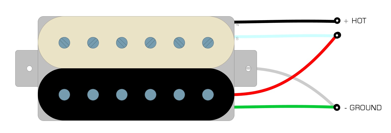
We’ll begin the Seymour Duncan Pearly Gates wiring by considering the Black Wire to be the Hot Wire. We solder the Red and White wires together and tape them off. Finally, we use Green as the Ground wire.
It’s a widespread practice to solder the Green and Bare wires together. (Fig 2)
Fig 2
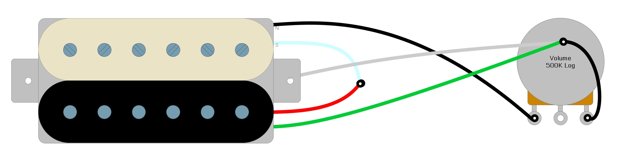
Now we’ll connect the positive (Black) and the negative (Green) wires to our pickup. First, solder the Green and the Bare wires to the back of the Volume Pot. (Fig 3)
Fig 3
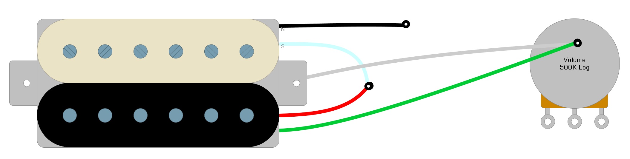
Next, solder the Black Wire to the first tab on the Volume control. Solder the third tab to the back of the volume pot, either with a short wire or by physically bending the connection tab until it contacts the casing of the potentiometer. (Fig 4)
Fig 4
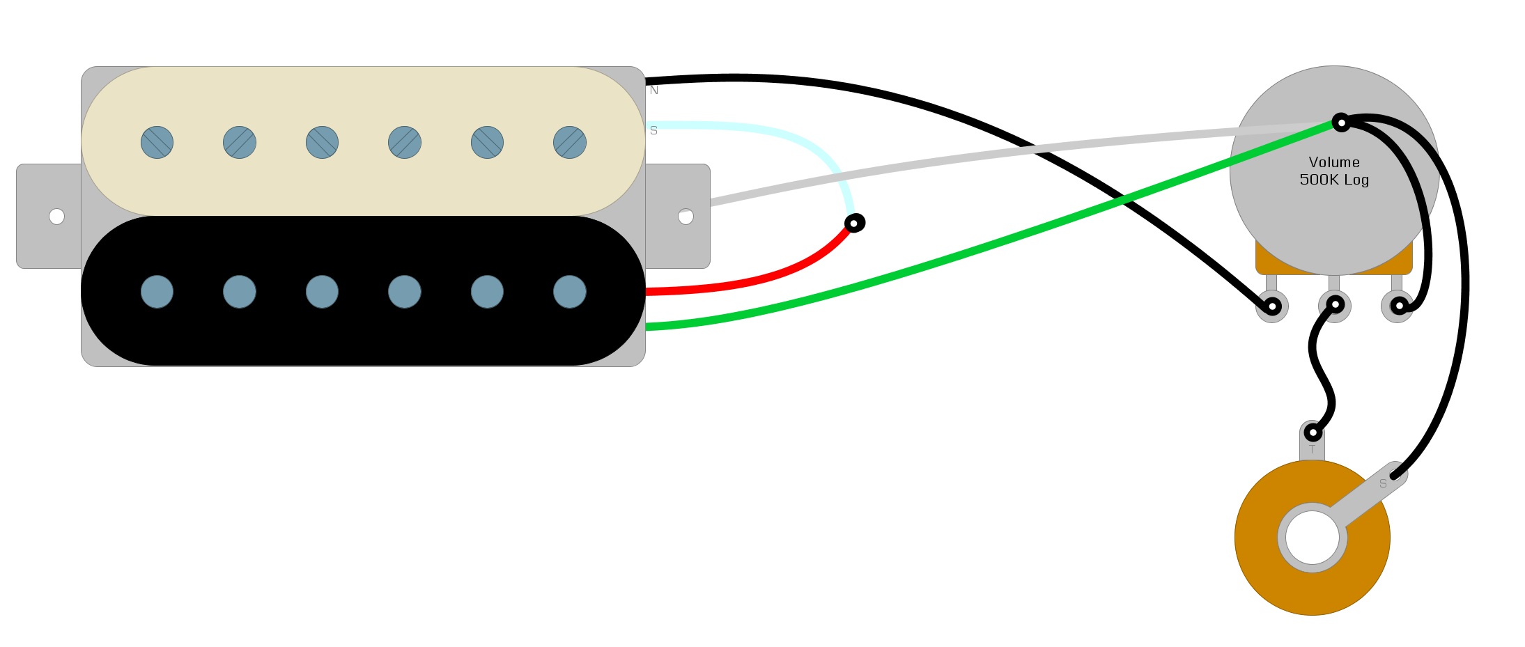
Next, we need to connect one wire from the center tab of the Volume pot to the Output jack, and then we need one that runs from the Output jack to the back of the Volume control. (Fig 5)
Fig 5
And now, your Installation is complete!
Summary
These instructions are the most basic for wiring a humbucker pickup. Adding a Tone Control will only add another potentiometer and a few capacitors. If you have more than one pickup, all of the positive wires will go to the switch. The switch will decide which pickup signal will get sent to the Volume control, and from then on the circuit will be the same as presented here.
Look around humbuckersoup.com for many other ways to wire your humbucker, open up your tonal possibilities, and search for your unique sound.
See you next time!