By Ed Malaker
Posted 09/28/2019
This time around, we’ll be looking at how to wire a DiMarzio Virtual Vintage Blues 2 in your guitar. The Blues 2 is a stacked humbucker that uses Alnico 2 magnets for higher gain, and it works just as well in the neck position as it does in the bridge. It’s known for a warm sound that doesn’t become muddy, even when heavily distorted. This makes it an excellent choice for Metal or Blues. Four colored conductor wires and a bare wire are used to install this pickup.
The Wires
The four colored wires are called “conductors” because each carries electricity to and from the two coils in the humbucker. Each coil needs to have one positive and one negative wire. The color that goes to each is what we call the pickup’s “Wiring Code.” Unfortunately, there is no standard Wiring Code, and the color combination varies between manufacturers and sometimes between different models of the same manufacturer.
The Bare wire is the pickup Shield. Its primary purpose is to trap radio frequencies and other interferences that reach the pickup’s cover and shuttle them to ground before they penetrate the coils and degrade your signal. The Shield and the pickup coils are not connected, but the Shield does get soldered to ground.
The Wiring Code
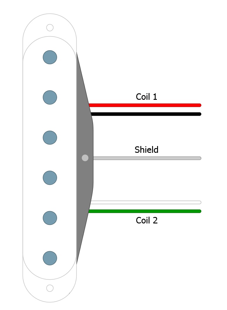
In this pickup, one coil uses Green and White while the other uses Red and Black (Fig 1).
Fig 1
Humbucker coils are Series wired, which means that we run one coil right into the other to create one long continuous path for our signal to travel. Combining them makes the humbucker almost twice as loud as a single-coil pickup. It also helps give the humbucker its warmer tones due to phase cancellation caused by two coils in the proximity of one another.
Getting Started
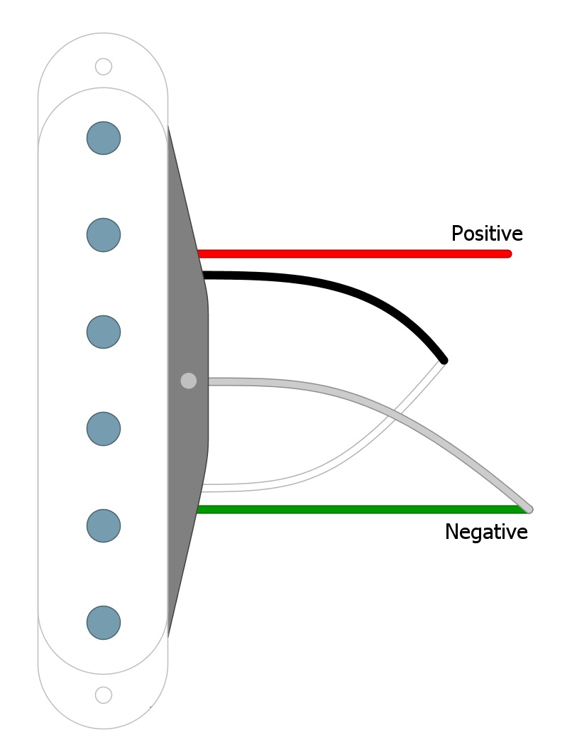
We begin our wiring by identifying the Red wire as the Hot. We solder the Black and White wires together and tape them off. Then finally, we use Green as the Ground, and as standard practice, we solder the Green and Bare wires together (Fig 2).
Fig 2
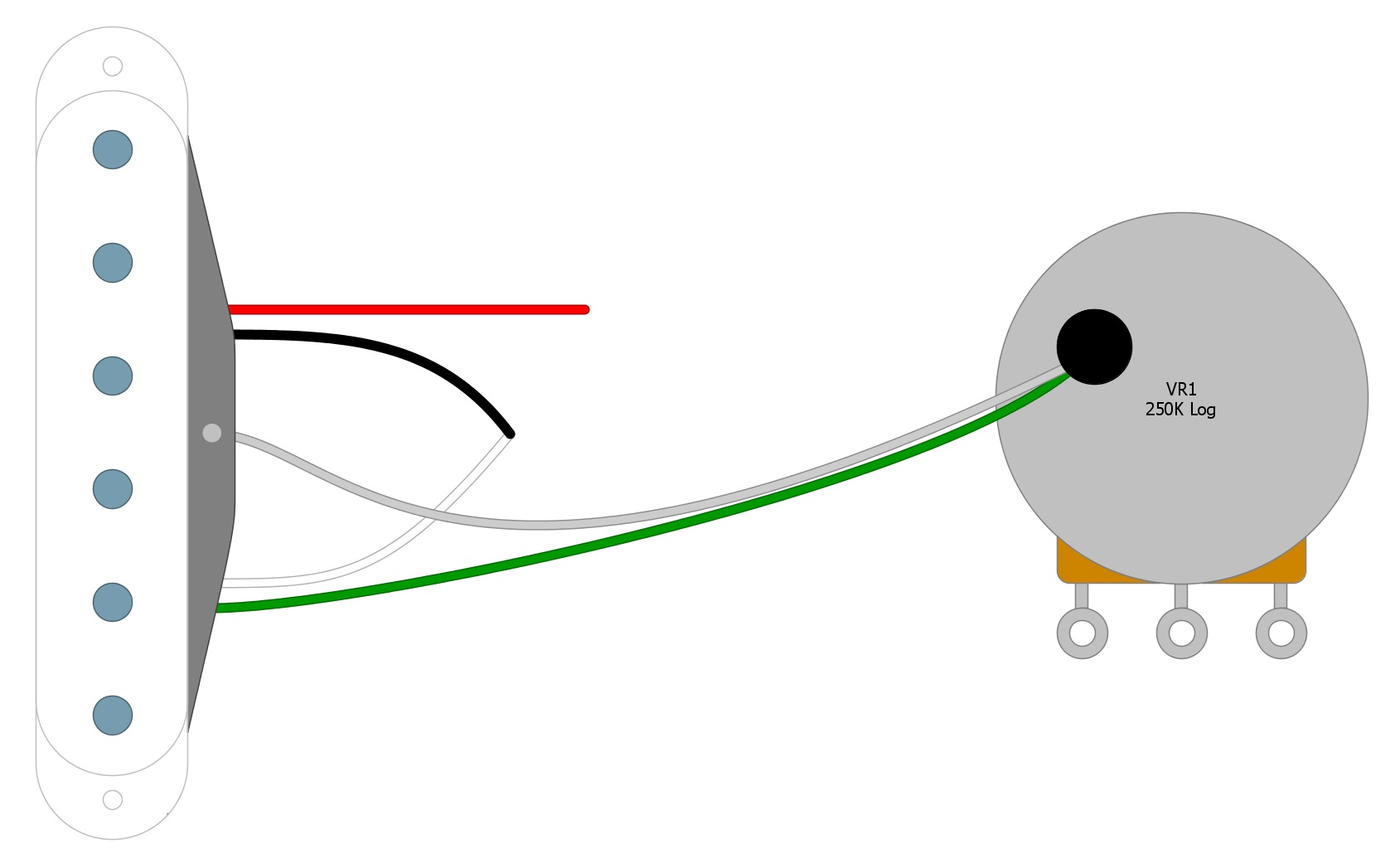
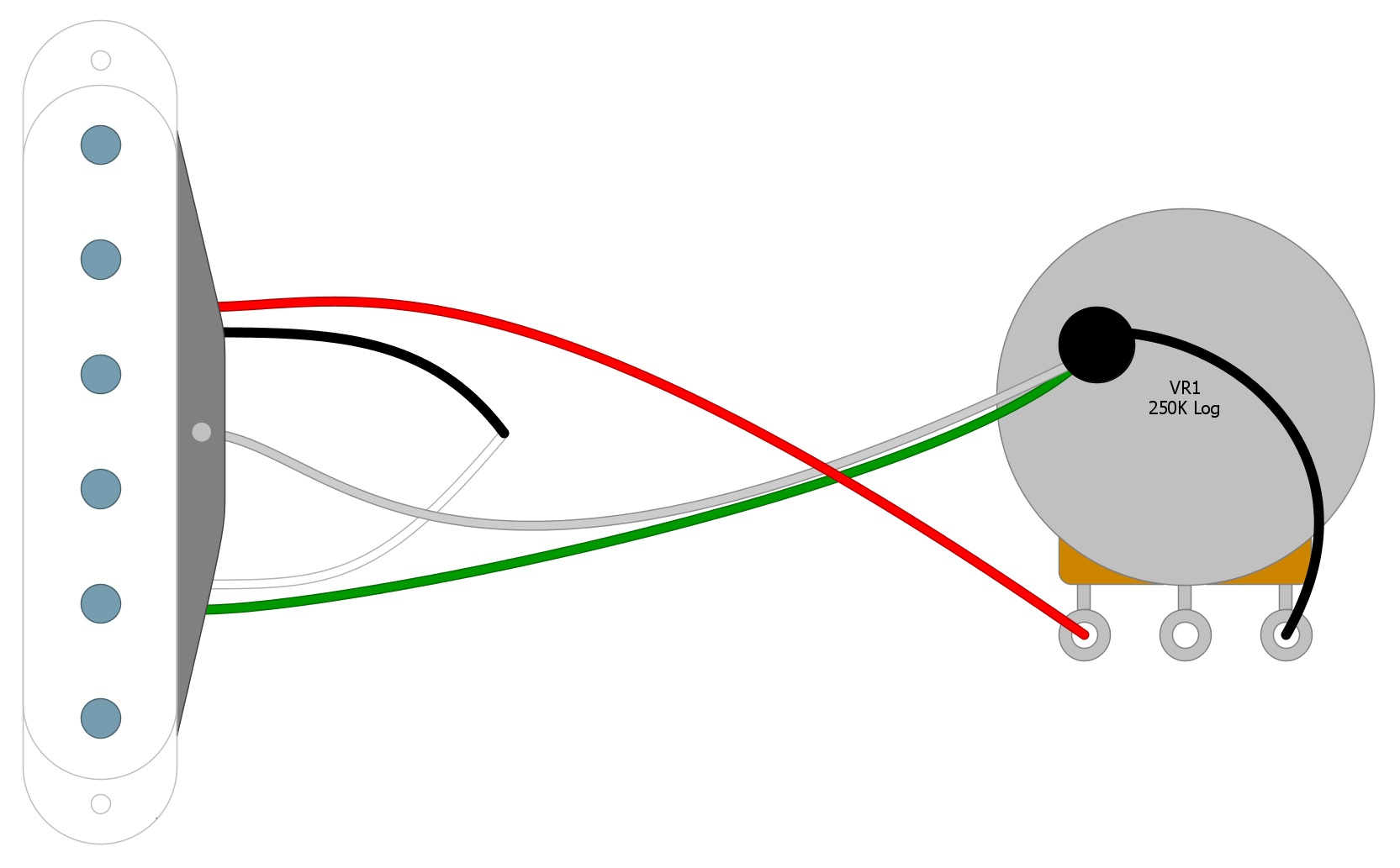
Now we’re left with the positive (Red) and negative (Green) wires that will be needed to install our pickup. Solder the Green and the Bare wires to the back of the Volume pot, which is the standard place to solder all of the ground wires (Fig 3).
Fig 3
Next, solder the Red wire to the first tab on the Volume control. Then solder the third tab to the back of the Volume pot, either with a short wire or by physically bending it until it contacts the casing of the potentiometer and can be soldered in place (Fig 4).
Fig 4
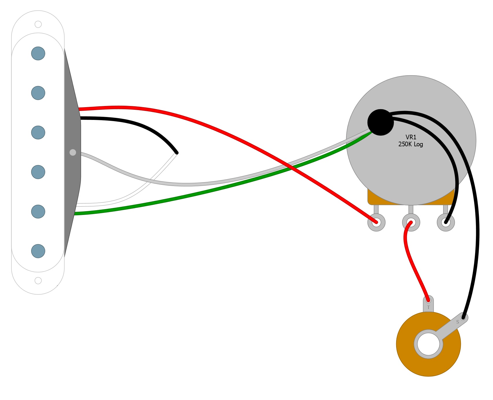
Next, solder one wire from the center tab of the Volume pot to the Output jack. Then solder another wire from the Output jack to the back of the Volume control (Fig 5).
Fig 5
Project complete!
Summary
This is the standard way to wire a humbucker pickup. If you want to add a Tone control, multi-pickup selector switch, etc., you’ll just be adding more components that will get soldered to the Volume control. This primary circuit, however, will not change. For example, if you have more than one pickup, all of the positive wires will go to the switch. The switch will decide which pickup signal will get sent to the Volume control. From then on, the circuit will be the same as presented here.
If you’ve enjoyed this article and found it helpful, please feel free to share this with your friends on Facebook and Twitter. For more articles on guitar electronics, visit humbuckersoup.com.