By Ed Malaker
Posted 05/25/2019
In this post, we’ll show you how to wire a DiMarzio IGNO for your guitar. This pickup features DiMarzio’s patented dual-resonance design and scatter-wound coils, and it uses Alnico 8 magnets for greater output. The DiMarzio IGNO is a new humbucker developed for Polyphia guitarist Scott LePage.
Overview
The IGNO can be wired in many different ways, because of its four-colored lead wires and one bare wire, but this time we are going to focus on the most straightforward way. We hope that this will help you understand the pickup better and open up the other wiring options.
Getting Started
Why are there so many wires? The first wire that we want to understand is the bare one. This is a shield wire, and it does not have a covering because it is not intended to carry any current.
Shield Wire
The shield wire is always grounded, and its primary purpose is to lead outside interference like radio frequencies away from the pickup and your amplifier.
Lead Wires
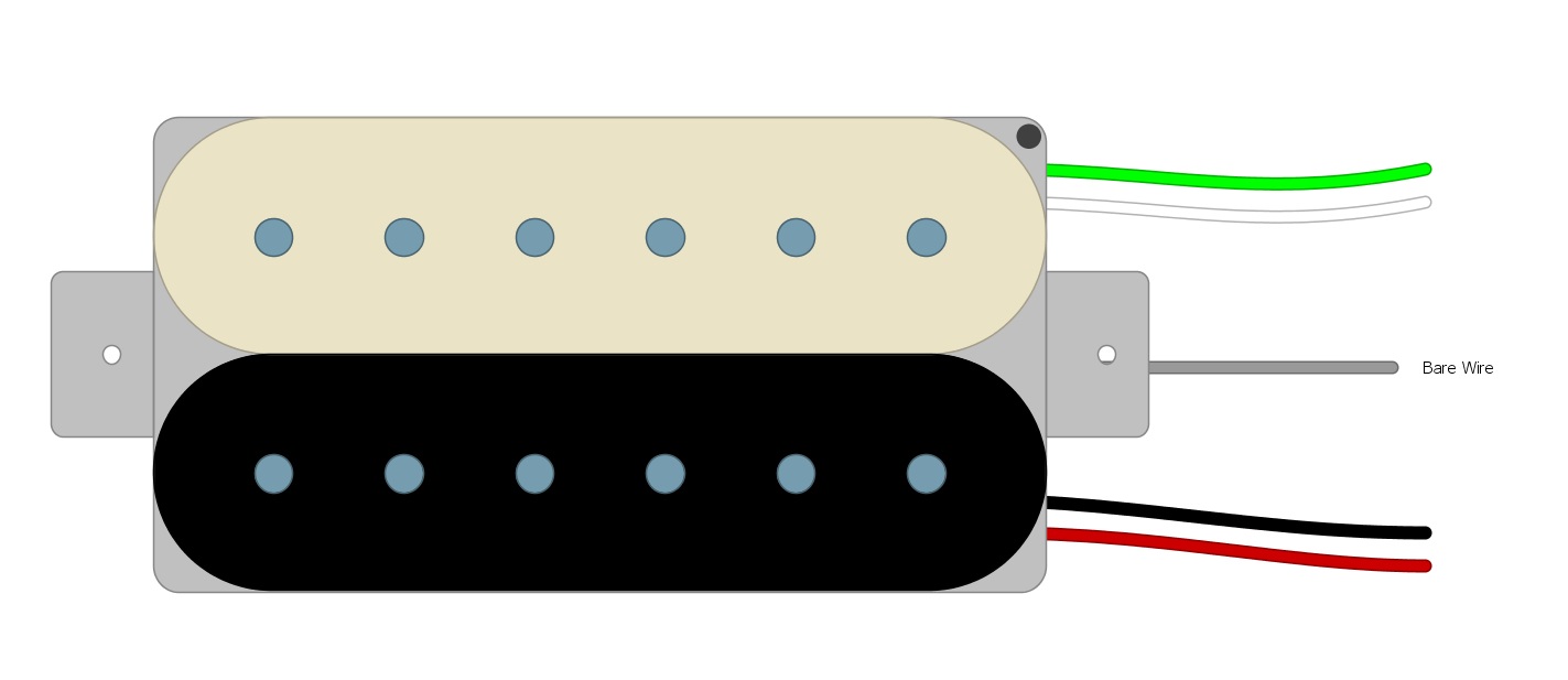
The remaining four wires are called conductors and they lead to the two coils. Each coil has one positive and one negative. Using a multimeter, you can run tests to help determine which wires lead to each coil. Since we are using a DiMarzio however, we can make it easy on ourselves and just look it up. For DiMarzio pickups, one coil uses Red and Black while the other uses Green and White (Fig 1).
Fig 1
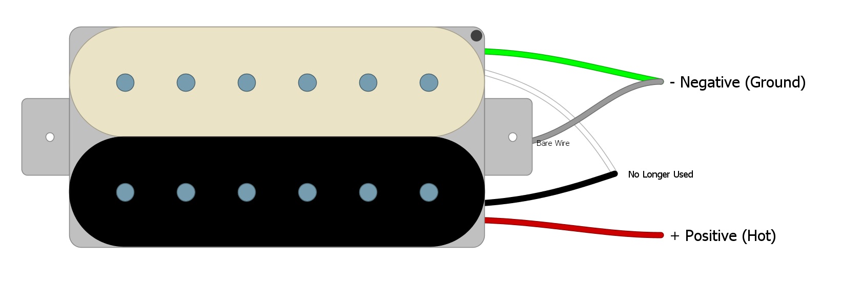
Series Wiring
The most common way to wire humbuckers is in Series, which means that we run one coil right into the other to create one long continuous coil. We wire our pickup in Series by considering the Red Wire to be the Hot one. We connect the Black and White Wires, and we use the Green Wire as the Ground. Most people join the Green and Bare Wires (Fig 2).
Fig 2
 You might also like this HumbuckerSoup article: Humbucker Pickup Splitting — Which Switch to Use
Now we’re left with the positive and negative wires that we will need to wire our pickup, in most cases. Whether we go directly to the Output Jack, to a Volume Control, or a switch, these are the only wires we need. Here’s how we can wire them to a Volume Control.
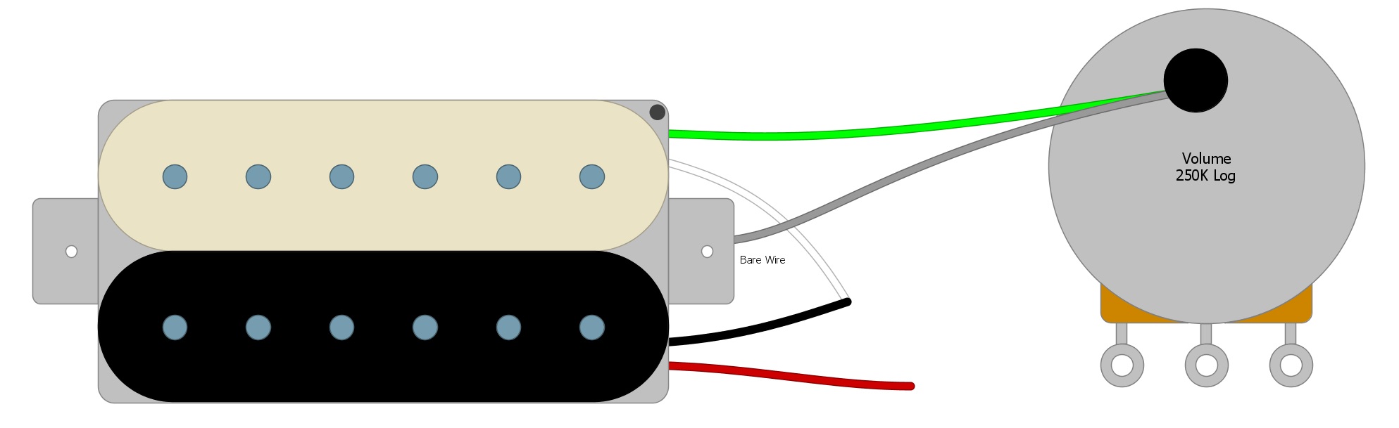
So, first, we will solder the Green Negative Wire and the Bare Wire to the back of the Volume Pot (Fig 3).
Fig 3
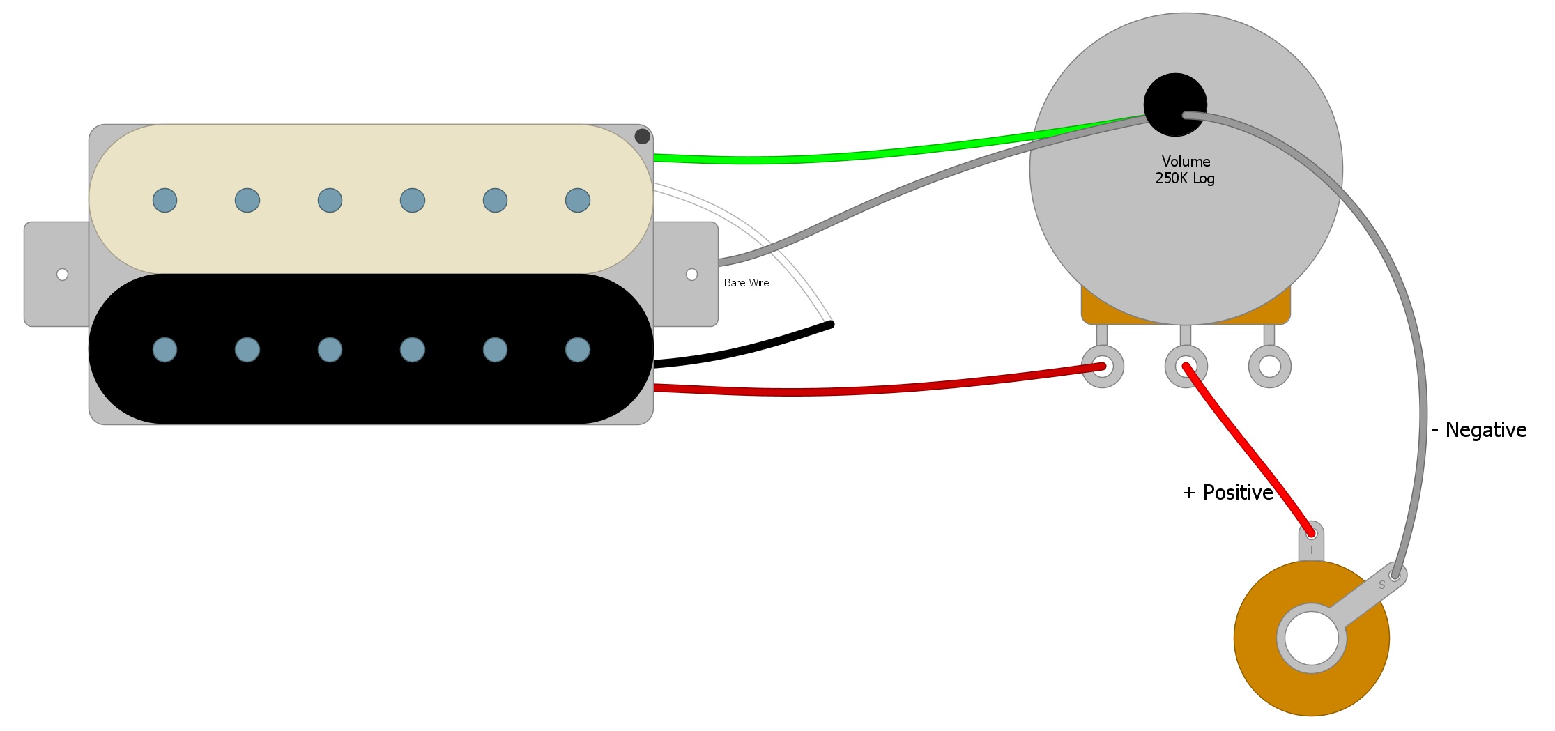
Next, we will solder the Red Positive Wire to the first tab on the Volume Pot (Fig 4).
Fig 4

Next, we connect the Volume Control to the Output Jack with another Positive Wire and another Negative Wire (Fig 5).
Fig 5
Adding a Tone Control or a Switch will only add components to this circuit. No matter how complicated things get, this circuit will be the lifeline that delivers the guitar signal to the amplifier.
If you’ve found this article helpful, please feel free to share this with your friends on Facebook and Twitter. For more articles on guitar electronics, visit humbuckersoup.com.