By Ed Malaker
Posted 04/01/2020
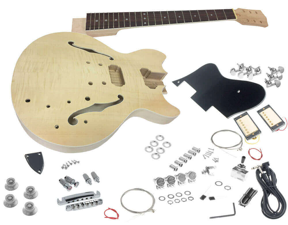
In this post, we’re going to look at a SOLO ESK-35 wiring diagram. The SOLO ESK-35, which is a kit guitar, is a clone of an ES-335 style semi-hollow body guitar. These guitars use two humbuckers. Each pickup has a volume and tone control, and a three-way toggle switch allows you to select which pickup is active. The setup is quite similar to the Gibson Les Paul.
ES-335 semi-hollow-body guitars are challenging to work with, because they require you to connect all of the wires and solder them before you install them into the body of the guitar, except for the pickups. Let’s go over the solo ESK-35 wiring diagram first and then we will give you some tips on getting the electronics into your guitar.
Unique Wiring
Before we talk about our SOLO ESK-35 wiring diagram, we would like to mention how unique it is. In most cases, you would wire this type of guitar exactly the same way you would wire a Gibson Les Paul or a Gibson SG; Epiphone guitars use a slightly different but overall similar wiring. Either of these diagrams would typically work for this guitar style. However, we saw some differences in the SOLO ESK-35 wiring diagram and wanted to help explain it.
Wiring Code
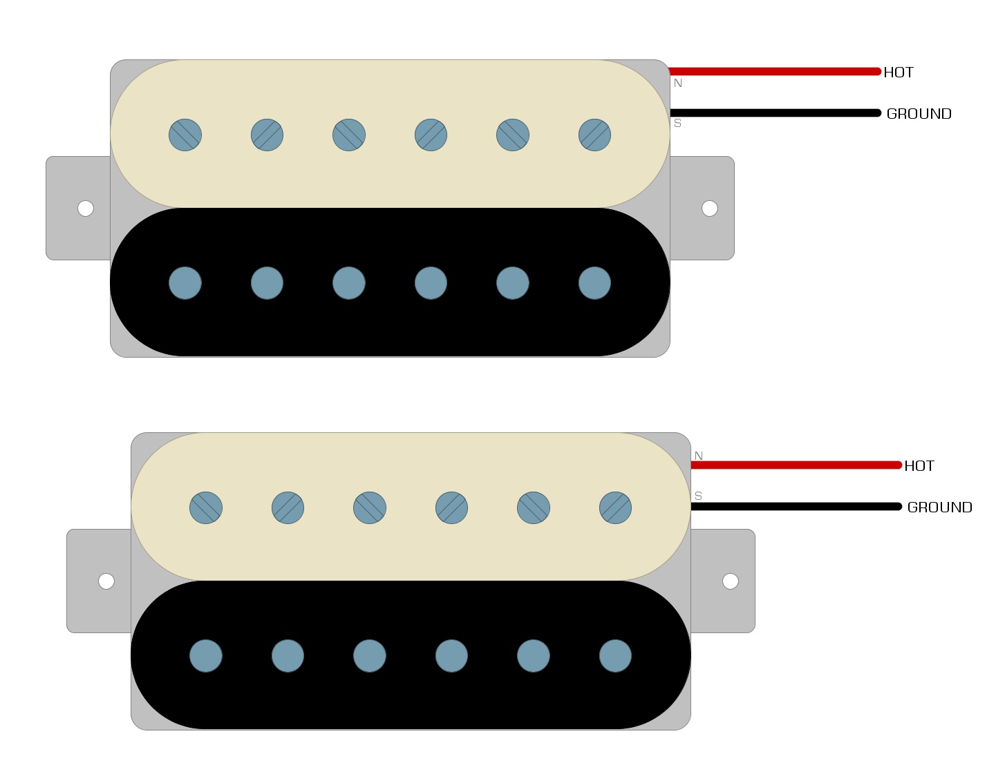
Humbucker pickups have two coils, which means that in most cases they have four colored wires, plus one bare wire. Two of the colored wires are connected and taped off, leaving two-colored wires and a bare wire. One colored wire is the Hot wire, and the other is the Ground. We connect the bare wire to the Ground wire leaving only two wires, Hot and Ground.
Unfortunately, every manufacturer uses different colored wires, so you will need to check the documentation of your pickup to know which wires are tied off, and which are the Hot and Ground. Our diagram is going to assume that you know which wires are which, and we’ll only show the Hot and Ground in our examples, as we do in Example 1.
Example 1
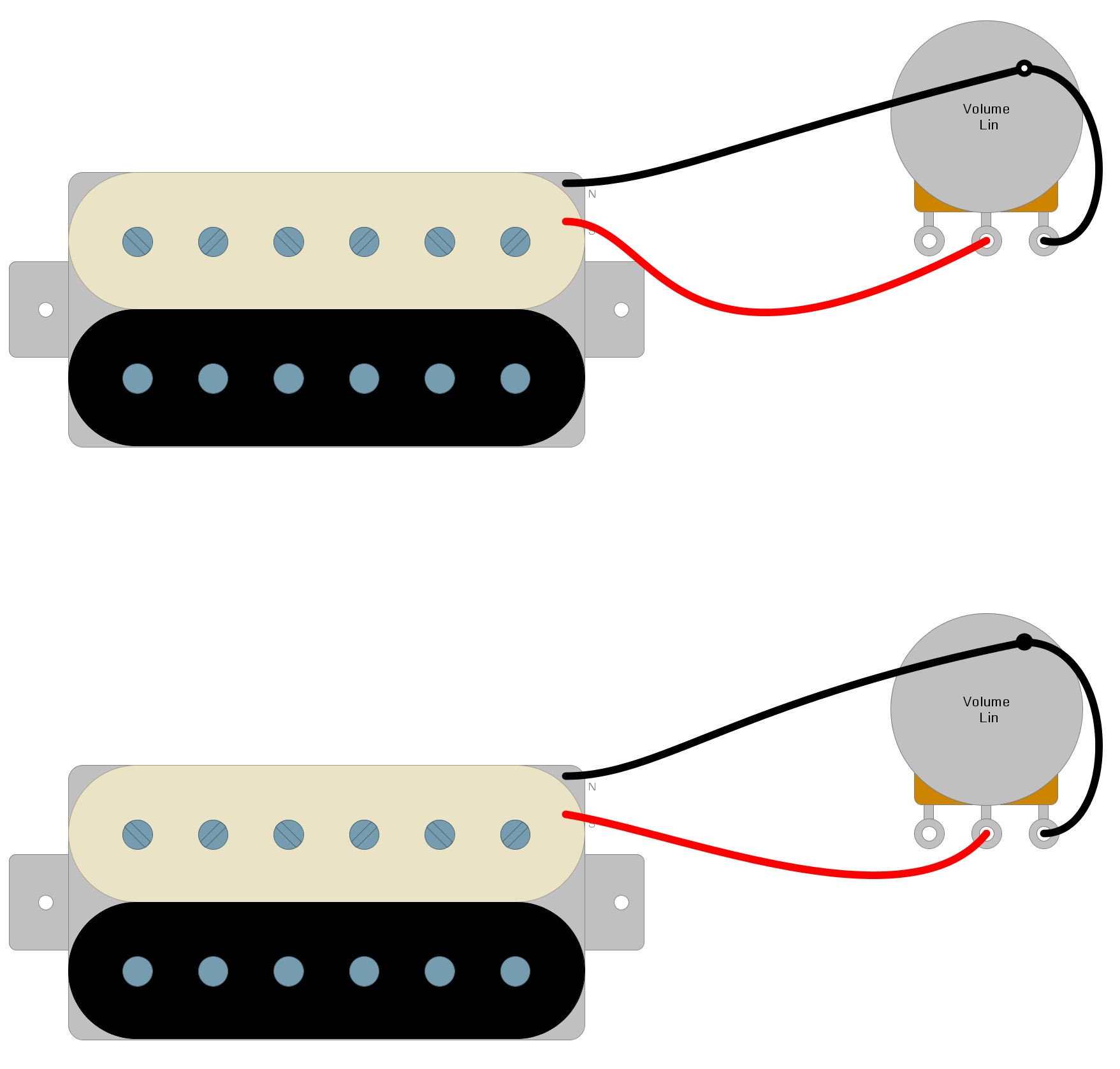
Volume Control
In guitars with several pickups that share the same Volume and Tone controls, the Hot pickup wire would go to the switch, but since there is a Volume and a Tone for each pickup, we send the Hot pickup wire directly to the Volume control. We solder the Ground to the back of the Volume pot. We do the same thing for both pickups, as we see in Example 2.
Example 2
When you look at Example 2, you will notice the extra Ground wire added from the third lug on the Volume pot to the back of the Volume pot. You can use a wire, but most people accomplish this connection by physically bending the lug until it makes contact with the case and soldering it in place.
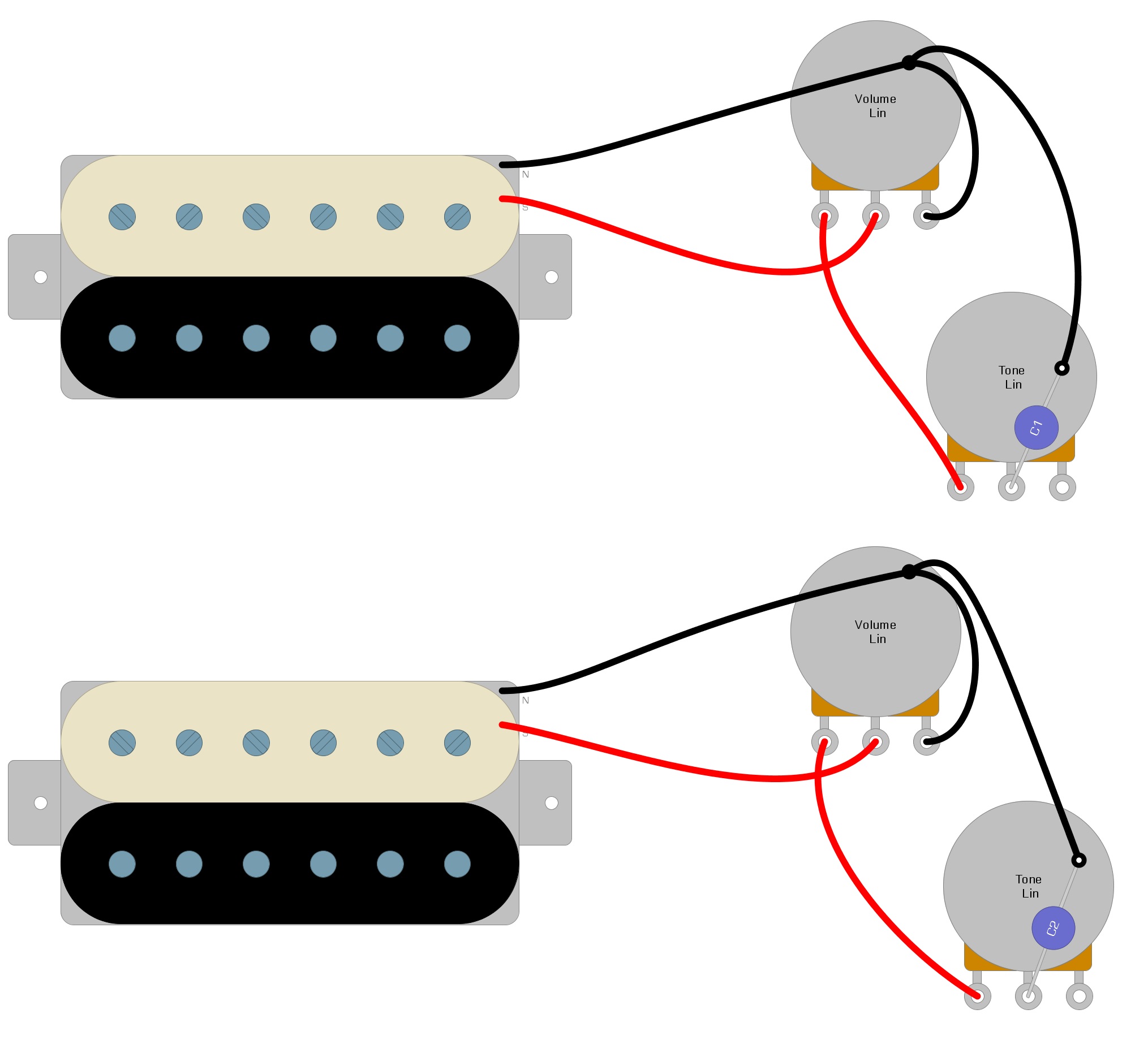
Tone Control
To add the Tone controls to your circuit, use Example 3 as a guide. You will be adding a capacitor to the circuit, but in most cases, it doesn’t matter which direction you place it in.
Example 3
Toggle Switch
To add the toggle switch, use Example 4 as a guide.
Example 4
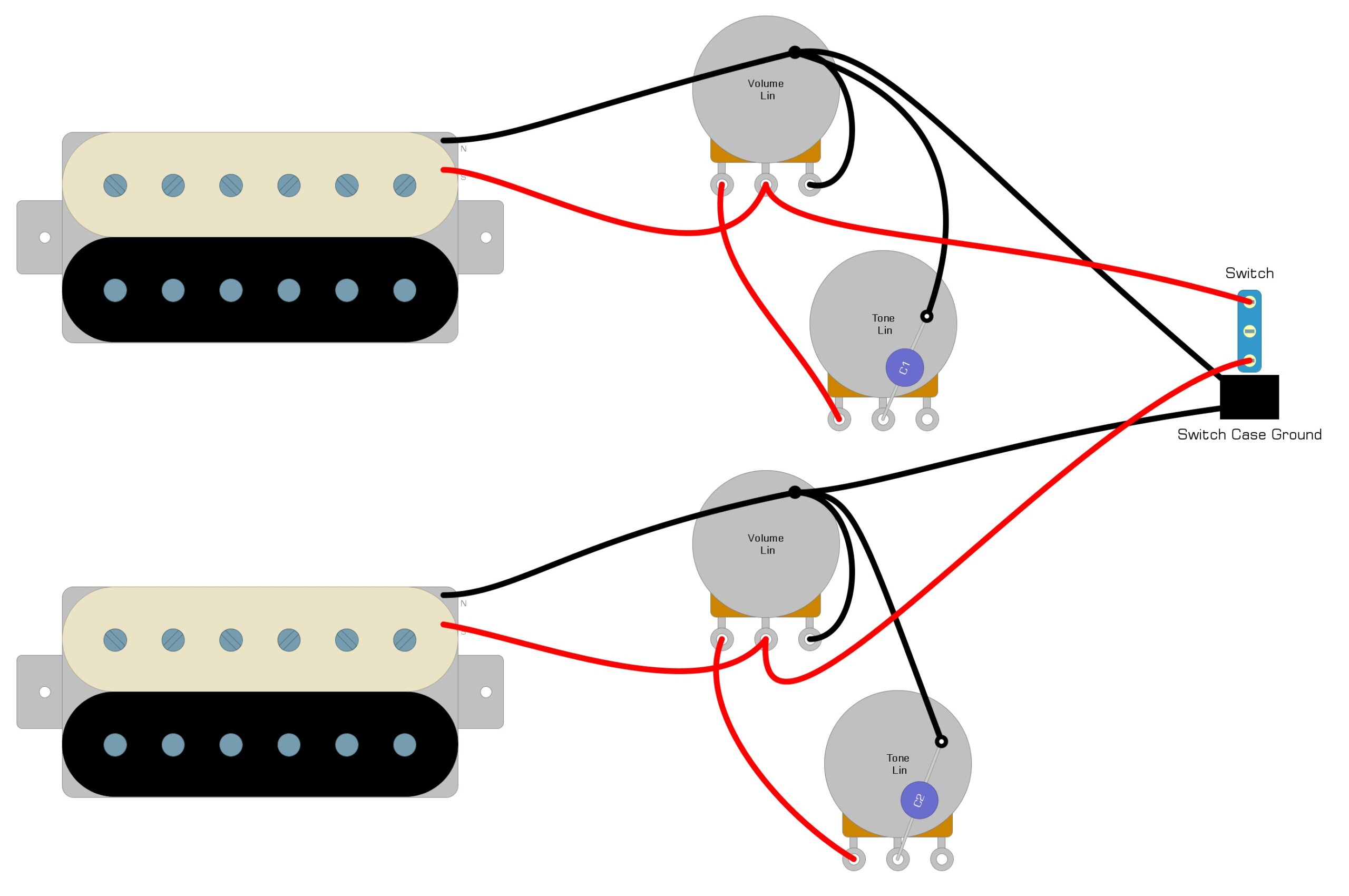
In Example 4, we add two wires to connect the toggle switch, but notice that we also add a Ground wire from the back of one Volume control to the back of the other.
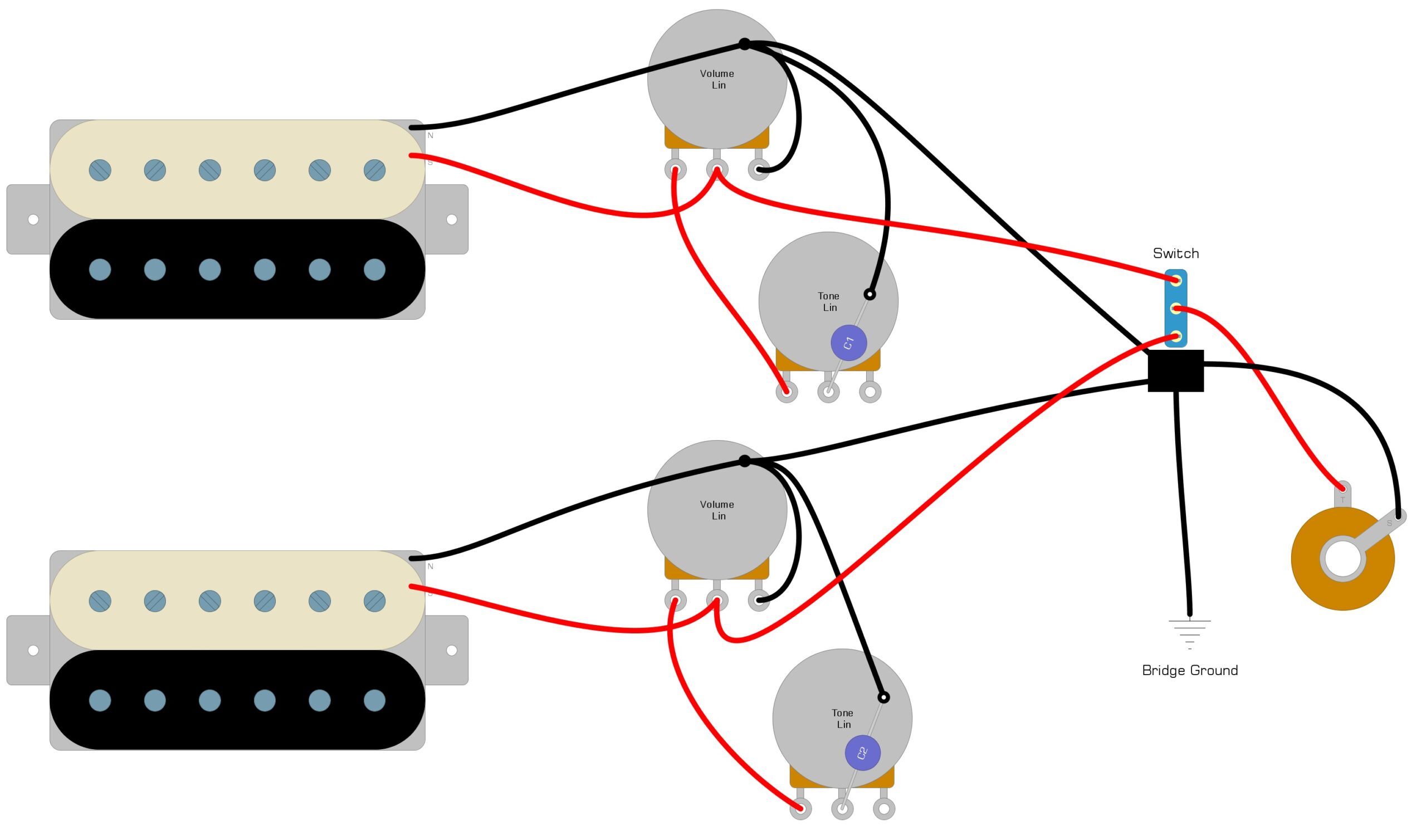
Output Jack
The last component we need to connect is the output jack, and you can use Example 5 as a guide.
Example 5
Installation Tips
Wiring up a semi-hollow body guitar can be extremely challenging because there’s nothing to hook the electronics to or hold the parts steady as you work. We’ve outlined a few tricks you can use to help make the process a lot easier:
- Install the pickups first.
- Use tracing paper to trace the hole configuration of your guitar.
- Transfer the sketch to a piece of cardboard and attach your volume and tone controls to that, so you can solder your connections using the correct lengths of wire.
- Tie a foot or two of fishing line, string, or yarn around the threaded part of each volume and tone control. Do the same for the output jack and toggle switch. As you tie the line around each component, feed the other end through the appropriate hole.
- When the lines are in place, gently work all of the parts into the F-holes and move them into position.
Conclusion
As you may have noticed from reading over this article on a solo ESK-35 wiring diagram installation, assembling the electronics in a semi-hollow body guitar can be quite challenging, and we don’t recommend doing it until you’ve done some work on other guitars first. Getting all of the components through the f-holes and into place can weaken and break soldering connections. Tracking them down and fixing them is a nightmare once everything is in place, so you want to know what you are doing before you start. That said, installing the wiring on a semi-hollow body guitar is the kind of rewarding experience that only those who have done it can appreciate.
We hope you have enjoyed our short guide and have found it helpful. If we have helped you get your guitar working, please feel free to share this SOLO ESK-35 wiring diagram on Facebook and Twitter. For more articles on guitar electronics, visit humbuckersoup.com.