By Ed Malaker
Posted 02/26/2020
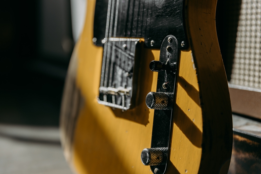
In this article, we’ll take a look at the unique design of the Fender Esquire guitar and walk through an unusual single pickup Telecaster wiring diagram. What makes the Fender Esquire so unusual? It’s a one-pickup Telecaster that features a three-way switch. For those unfamiliar with what this switch does, or how it can be added to a single pickup guitar, take a look at how we dissect this strange component.
Pickup Selections
Before we get to the diagram, let’s see what we get with each of the three pickup selections offered by the Fender Esquire.
Position 1
The first position sends the pickup through the Volume control only and bypasses the Tone control. Avoiding the Tone control results in a brighter tone. The first position produces the brightest tone available from the Esquire.
Position 2
The second position is in the middle and it runs the pickup through the Volume and Tone controls. This circuit is the same as Position 1 of the Fender Telecaster. The sound is still very bright but it’s warmer than Position 1.
Position 3
In Position 3, the pickup goes through the Volume and into a treble roll-off circuit. It does not use the Tone control in this position, and you cannot adjust the treble roll-off without changing components. Many players consider this position too dark and the resistor/capacitor values that create the roll-off have changed several times over the years. There are several modifications available for this position at humbuckersoup.com and scattered across the internet.
The Three Way Switch
As we get started, an understanding of the way the three-way switch works is important to know how this switching circuit works. We’ll try to explain it in the best we can without getting too technical.
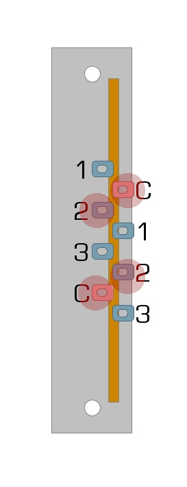
Your three-way switch is a two-stage switch, which means it’s two switches in one. This two-stage idea might make more sense if you look at Figure 1. Figure 1 is an image of a standard three-way switch.
Fig 1
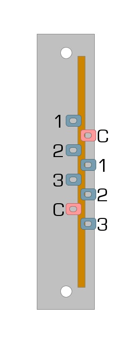
You can see how we have it labeled 1,3,5, C, and C,1,3,5. The C stands for Common, while the numbers represent the switch positions.
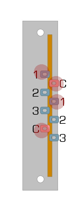
Common is always active, while the numbers are only active when the switch is in that position. For example, in switch Position 1, the Cs are active on both sides, as are the 1s, which are represented by the highlights in Figure 2.
Fig 2
In the second switch position, the Cs are active again on both sides, but this time the 2s are active, as seen in Figure 3.
Fig 3
You can probably guess which lugs are active in switch Position 3, so we can start to put that to work for us.
Step 1: Wiring Position One
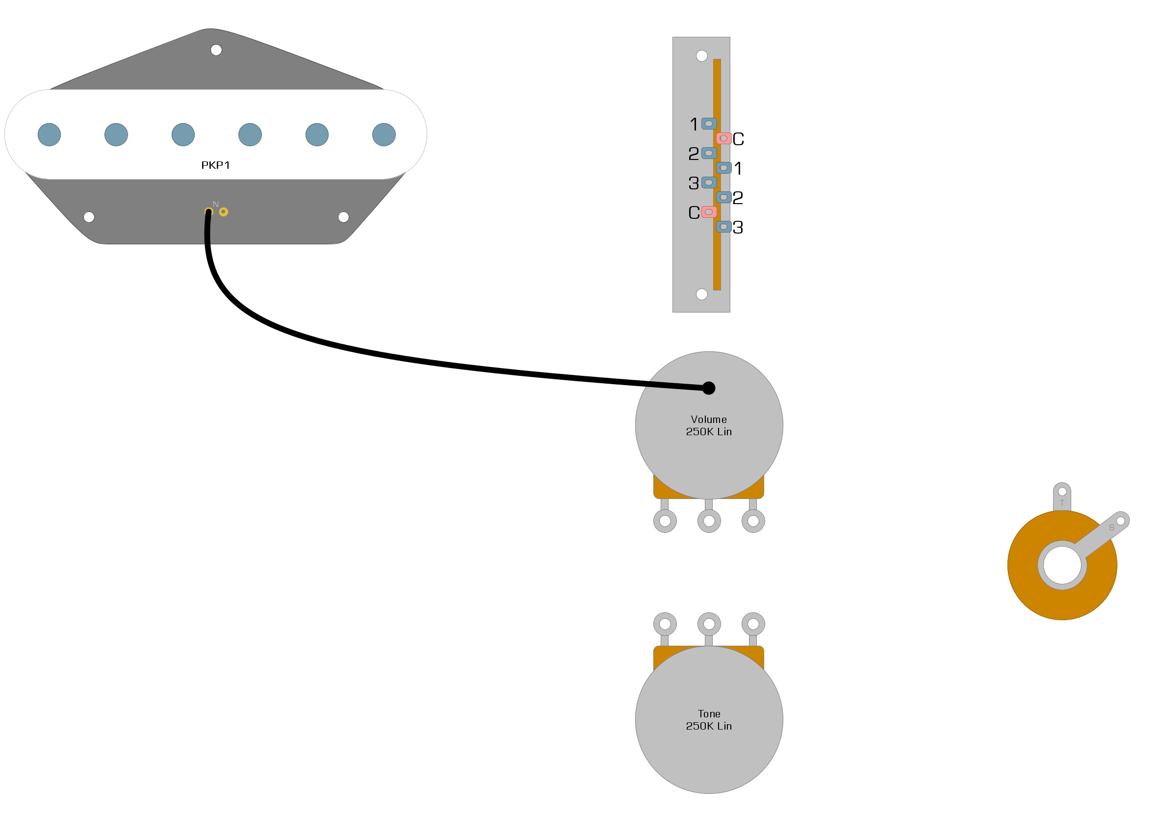
Let’s begin by connecting the pickup. On the early Esquires, the White wire was the Hot, and the Black wire was the Ground. Your guitar may be the same, but if it’s different, just look up your model number to get your wiring code.
Solder the Ground wire to the back of your Volume pot, as shown in Figure 4.
Fig 4
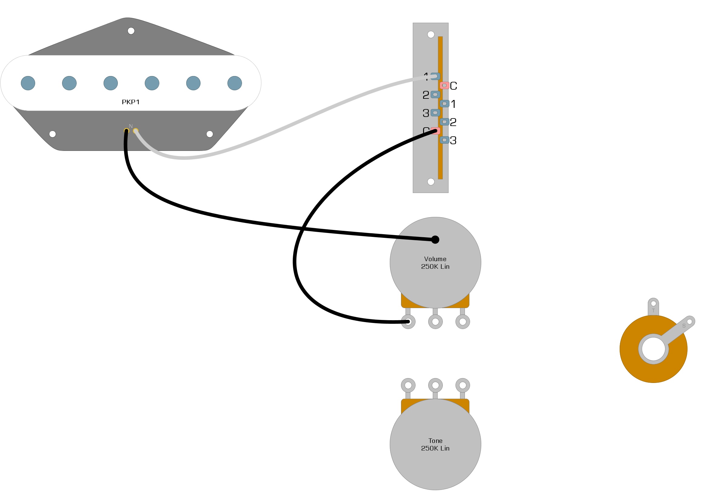
Now, connect the Hot-wire to Lug-1 on the left side of the three-way switch. Then, solder a wire from the common on the left side to Lug-1 on the Volume control, as seen in Figure 5.
Fig 5
Let’s add the rest of the wiring for Position 1. When complete, it should look like Figure 6.
Fig 6
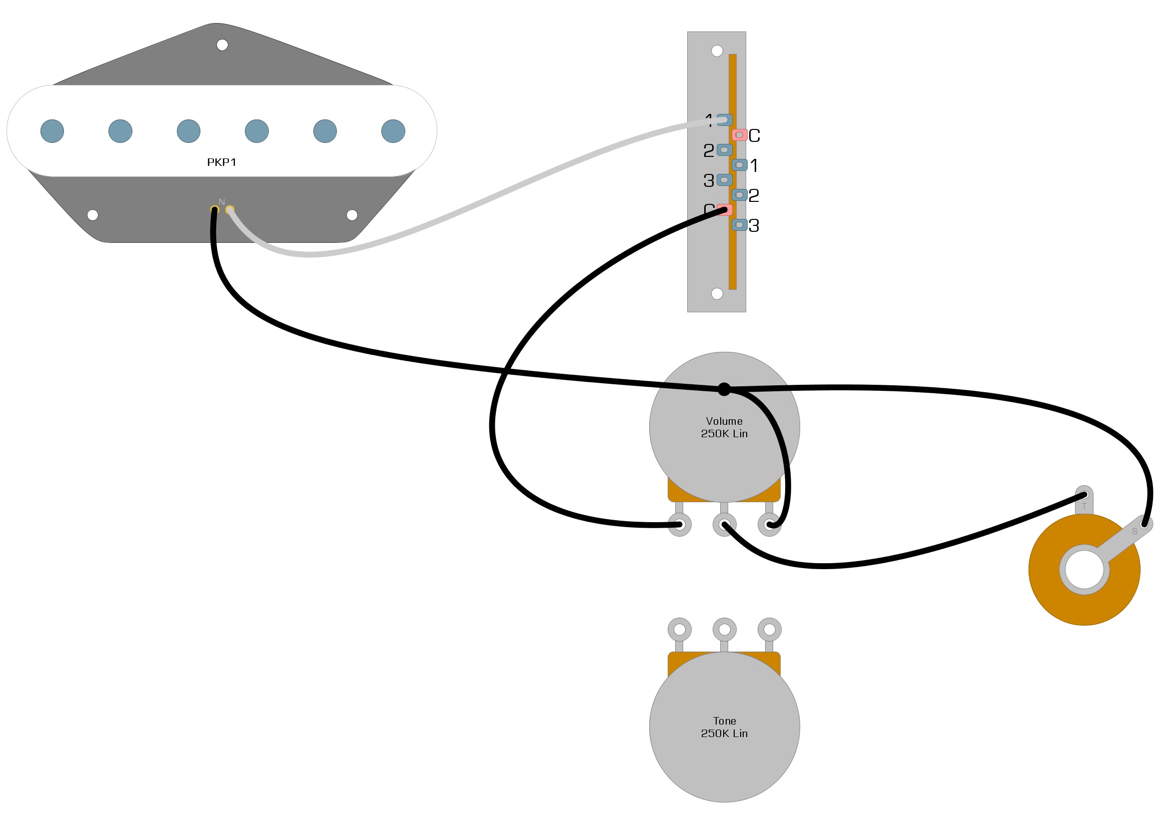
Position One Circuit Review
Let’s look at the circuit we created in Figure 6. In this circuit, the signal comes from the pickup and enters our three-way switch at Lug-1. If our switch is in Position 1, the signal will exit the switch through the common lug. If our switch is not in Position 1, the signal will stop at Lug-1.
Once the signal leaves the switch through the common lug, it travels to Lug-1 of the Volume control. The signal then leaves the Volume control through Lug-2 of the Volume control and goes to the tip of the Output jack, where it will continue to the amplifier. As you can see, there are no Tone control options in this circuit, and it operates just as we said it would earlier. The only high end we lose is a small amount through the 250k volume control. If we had used 500k pots instead, the tone would be a little brighter.
Step 2: Wiring Position Two
As we said in Step 1, the signal from the pickup is only being delivered to Lug-1 in our circuit so far. To have any sound when using Positions 2 and 3 of our three-way switch, we need to make the signal from our pickup available to those lugs as well.
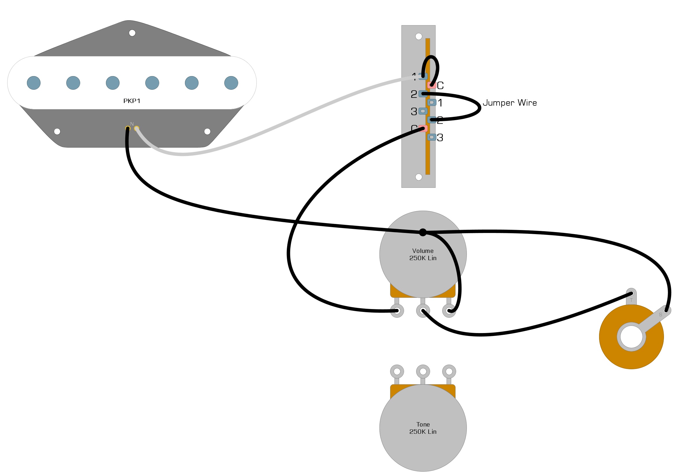
We can deliver the pickup signal to Lugs 2 and 3 by using the second stage of our three-way switch. All of our wires so far are attached to the left side of the switch, which is Stage 1. To start using Stage 2, we need to add a jumper wire from Lug-1 of Stage 1 to the Common Lug of Stage 2, as seen in Figure 7.
Fig 7
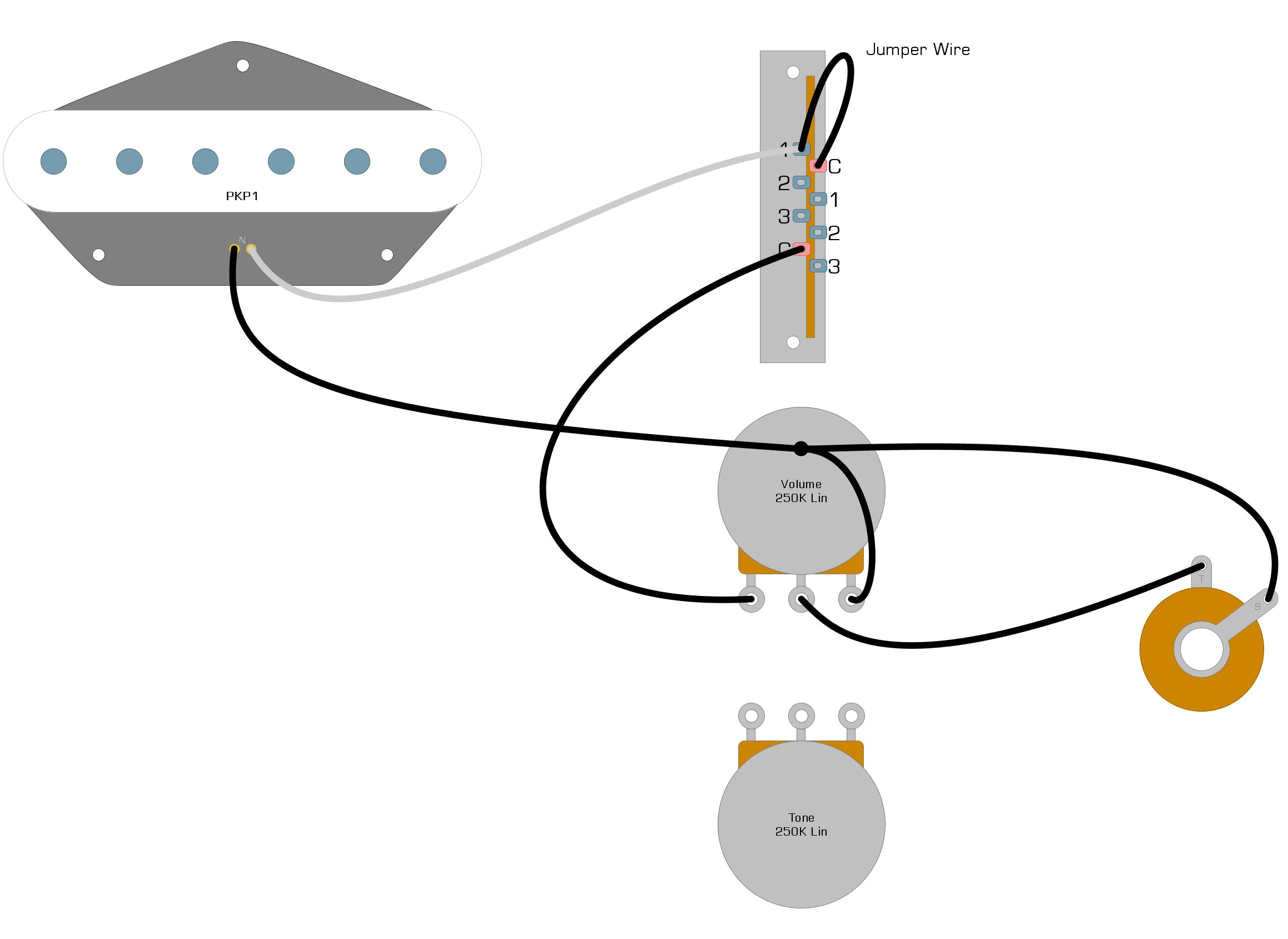
Figure 7 was a small modification, but it has a significant effect on our circuit. The signal now runs from our pickup to BOTH Lug-1 of Stage 1, and the Common of Stage 2.
This mod means that in switch Position 1, our signal will still enter the switch through Lug-1 and exit through the Common of Stage 1, but in the second switch position, we will now be able to access our pickup signal from Lug-2 on the Second Stage. In switch Position 3, we can obtain the pickup signal from Lug-3 on the Second Stage.
To use switch Position 2, we add another jumper wire. This time the jumper wire goes from Lug-2 of Stage 2 to Lug-2 of Stage 1. We can see this wire added to our diagram in Figure 8.
Fig 8
If you were to plug your guitar in now, you would find that Position 2 works, but sounds the same as Position 1, because they are the same. The signal comes from our pickup and enters the Common Lug of Stage 2. When the pickup switch is in the Second Position, the pickup signal travels from Lug-2 of Stage 2 to Lug-2 of Stage 1 and then exits the switch through the Common of Stage 1 and proceeds to the Volume control.
To add the Tone control, we add a jumper wire from Stage -1 Lug – 2 to Lug-3 of the Tone control pot, as we see in Figure 9.
Fig 9
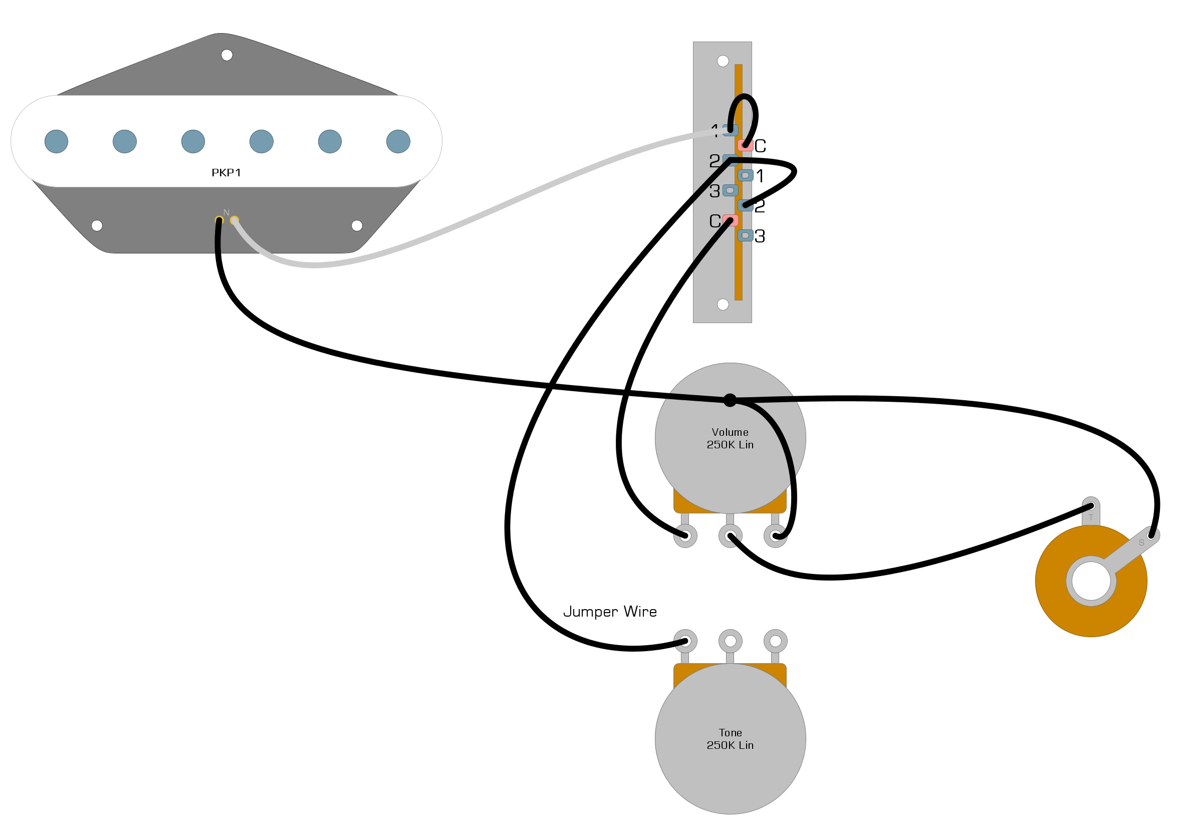
Once you have added the jumper wire to the Tone pot, we can finish the circuit by adding a capacitor to Lug-2 of the Tone pot and connecting it to the back of the Tone pot. Also, add a jumper wire from the back of the Tone pot to the back of the Volume pot. You can see these additional connections in Figure 10.
Fig 10
Position Two Circuit Review
When our pickup switch is in the second position, the signal goes from the pickup into the switch through the Common Lug of the Second Stage. The signal then leaves through Lug-2 of the Second Stage and enters Lug-2 of the First Stage. Once the signal enters Lug-2 of the First Stage, some of the high-end frequencies are allowed to escape to Ground through the Tone control. The rest of the signal will exit the switch through the Common Lug of Stage 1 and proceed to the Volume control.
Step 3: Wiring Position Three
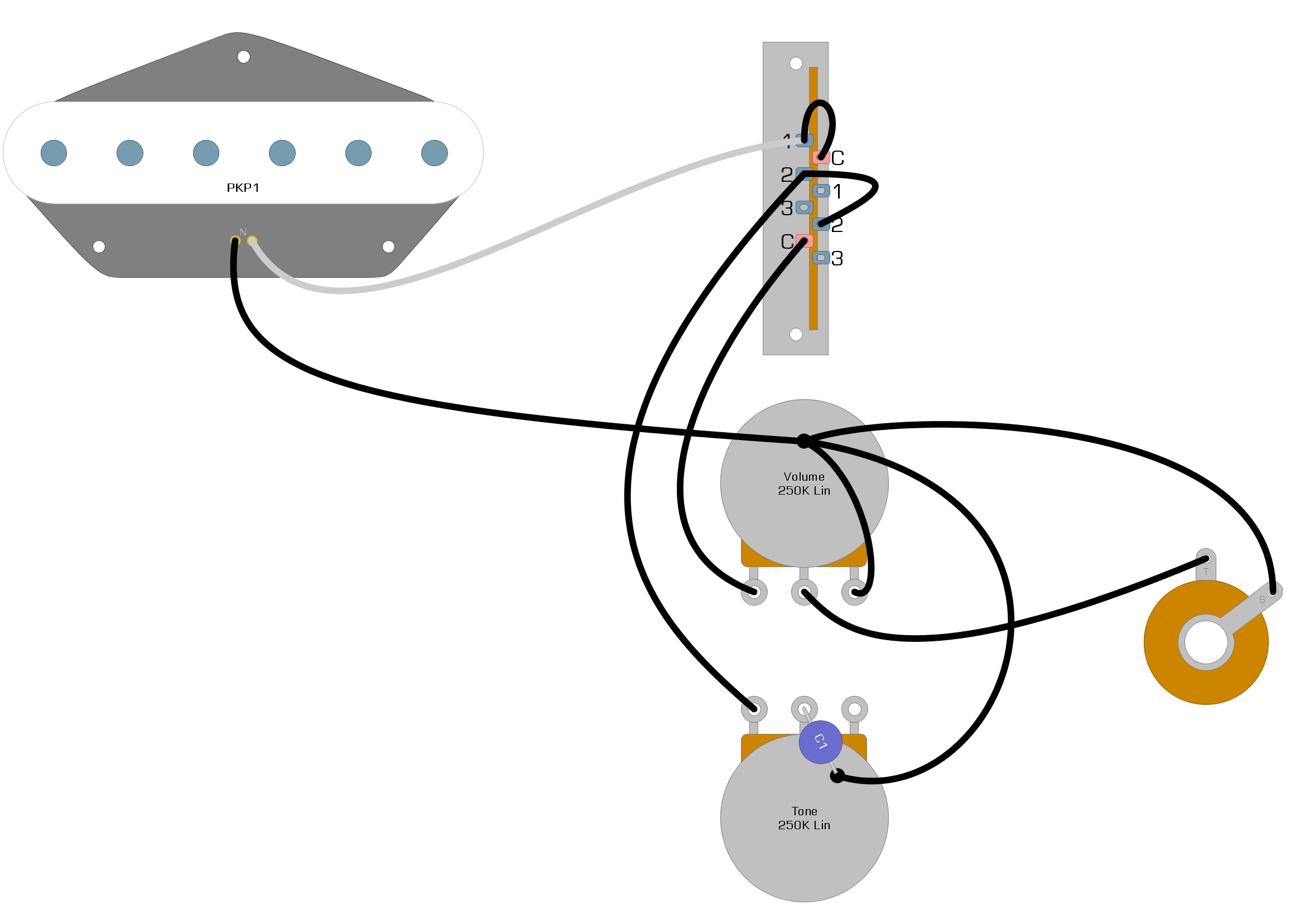
To complete our single pickup Telecaster wiring diagram and add switch Position 3, we connect a capacitor to Lug-3 of the Second Stage of our three-way switch. We connect the capacitor to a resistor, then connect the resistor to Lug-3 of Stage 1 of our switch. Next, we connect another capacitor between Lug-3 of Stage 1 and the back of our Volume control. We can see these connections in Figure 11.
Fig 11
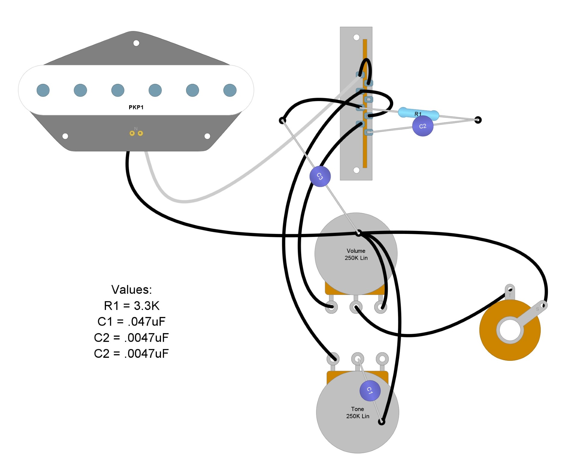
Position Three Circuit Review
When our pickup selector switch is in Position 3, the signal comes from our pickup and enters the switch through the Common Lug of Stage 2. The signal then leaves through Lug-3 of Stage 2 and proceeds through the resistor and capacitor, which filters out some high end. The signal enters the switch again through Lug-3 of Stage 1. At this time, more high-end frequencies will be allowed to escape through the capacitor that goes to the back of the Volume pot, and the rest will leave the switch through the Common Lug of Stage 1 and proceed to the Volume pot.
Final Steps
Figure 11 represents a complete diagram of the Fender Esquire circuit. There is a lot of debate on the values of the resistors and the capacitors in this circuit. They have been changed many times over the years. Using capacitor values of .047-uf with a resistor value of 3.3-k seems to be a good starting point for many people. You can adjust from there. Higher value resistors will lead to a brighter tone, while lower value capacitors will lead to a brighter tone.
Conclusion
We hope that you have enjoyed reading through this guide, and have learned something new about how three-way switches work. Leo Fender created something unique with this circuit, and not many other guitars can get three distinct tones from one pickup. This circuit also wants you to manipulate the values to improve the tone, which makes it even more fun.
If you’ve enjoyed this article and have found it helpful, please feel free to share this wiring diagram on Facebook and Twitter. For more articles on guitar electronics, visit humbuckersoup.com.