By Ed Malaker
Posted 07/27/2019
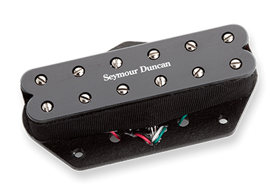
Looking to wire a Seymour Duncan ST59-1? Let’s start with some basics: the ST59-1 is a mini-humbucker, designed as a direct replacement for the bridge pickup in a Fender Telecaster, but it will also work well in many other situations. The ST59-1 offers players hum-free operation and a thicker tone that still retains plenty of Tele Twang. Here, we’ll install this pickup into your guitar using four colored conductor wires and a bare wire.
The Wires
The multiple-colored wires are a common source of confusion when installing any humbucker pickup. If you look at the “features” part of a humbucker description, you will often see that one of them is labeled “4-conductor wire.” The four colored wires are called “conductor” wires. They are called this because each of these wires carries current to and from the two coils in the humbucker. Each coil has one positive and one negative wire. So, which color is positive and which color is negative is called the pickup’s “Wiring Code.”
Unfortunately, there is no standard Wiring Code, and it varies between manufacturers. The Bare wire is the Shield, and it is not connected to the coils. Its primary purpose is to trap radio frequencies that reach the pickup and shuttle them to Ground before they degrade your signal. The Shield is always soldered to Ground.
Wiring Code
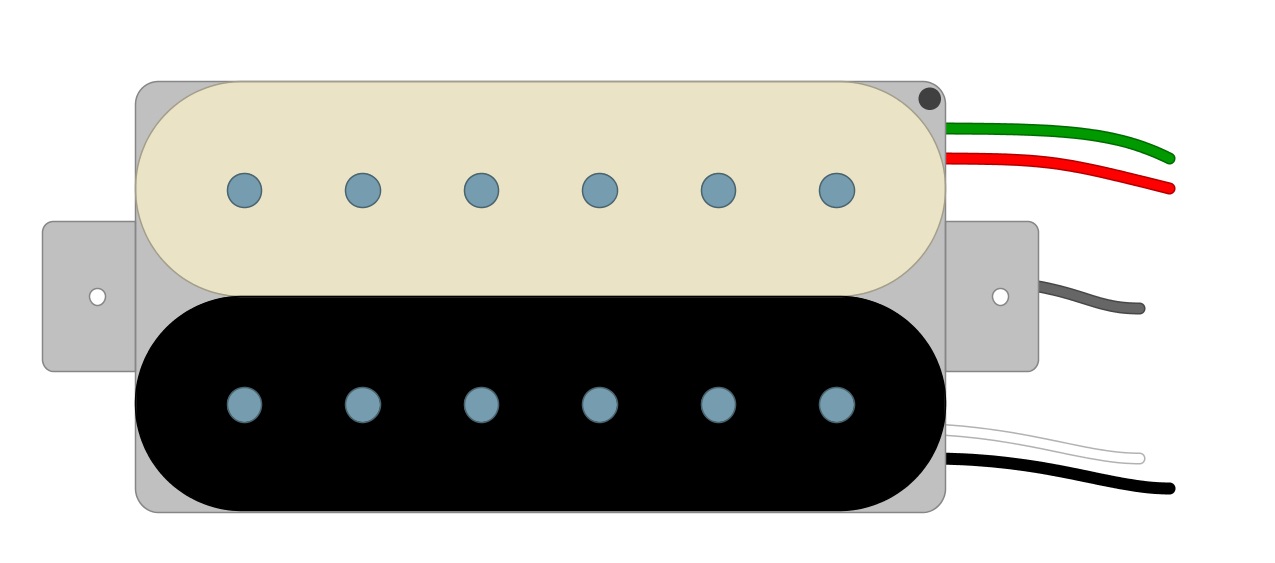
For the ST59-1, one coil uses Green and Red wires, and the other uses Black and White wires (Fig 1).
Fig 1
The “Standard” way to wire humbuckers is in Series. Note that series means that we run one coil right into the other to create one long continuous path for our signal to travel. This makes the humbucker almost twice as loud as a single-coil, and it is also responsible for its warmer tones. There are many different ways that we could wire it though, and that is the reason why we have so many wires. So, for now, we will do it the Standard way.
You might also like this HumbuckerSoup article: ST59-1 Little 59, by Seymour Duncan
Installation
We begin installing the ST59 by identifying the Black wire as the Hot. Then, we solder the Red and White wires together, tape them off, and use the Green wire as the Ground. It’s standard practice to solder the Green and Bare wires together (Fig 2).
Fig 2
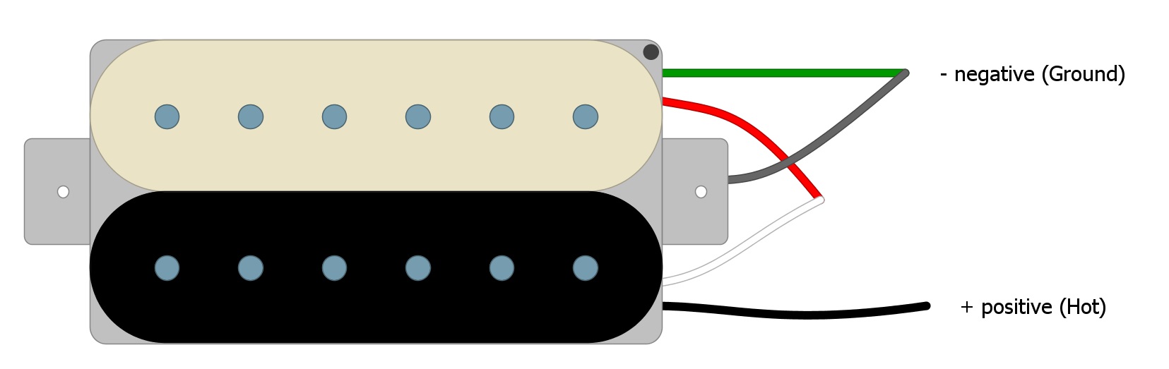
Now we’re left with the positive (Black) and negative (Green) wires that we will need to install our pickup.
Connecting to a Volume Control
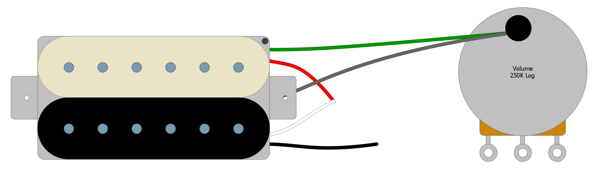
First, solder the Green Negative wire and the Bare wire to the back of the Volume pot, which is the standard place to solder all Ground wires (Fig 3).
Fig 3
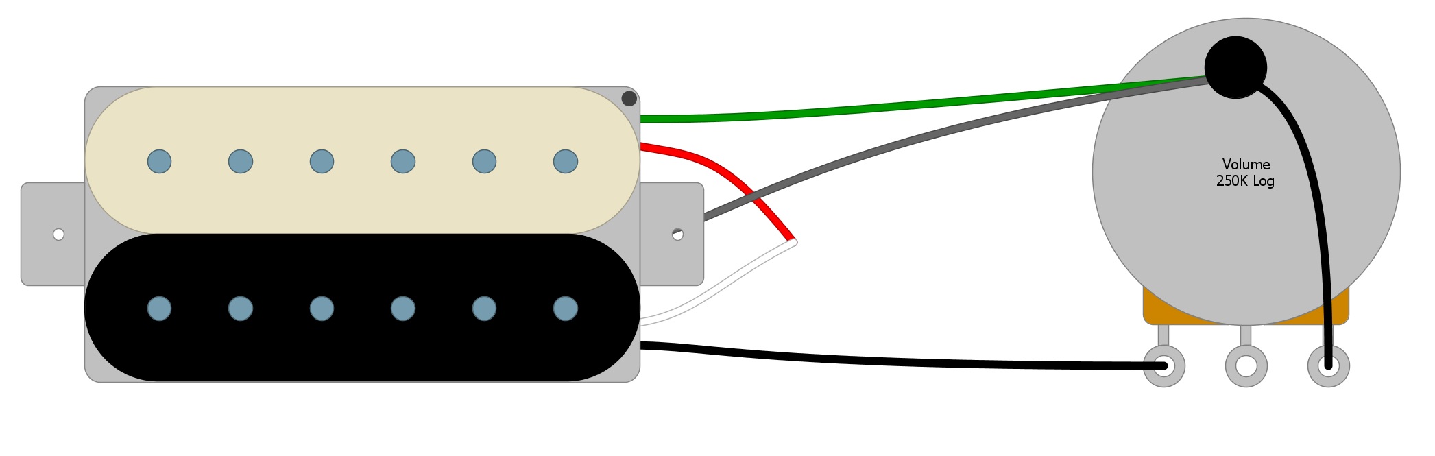
Next, we will solder the Black wire to the first tab on the Volume control. Most people solder the third tab to the back of the Volume pot, either with a short wire or by physically bending the tab until it contacts the back case of the potentiometer and soldering it in place (Fig 4).
Fig 4
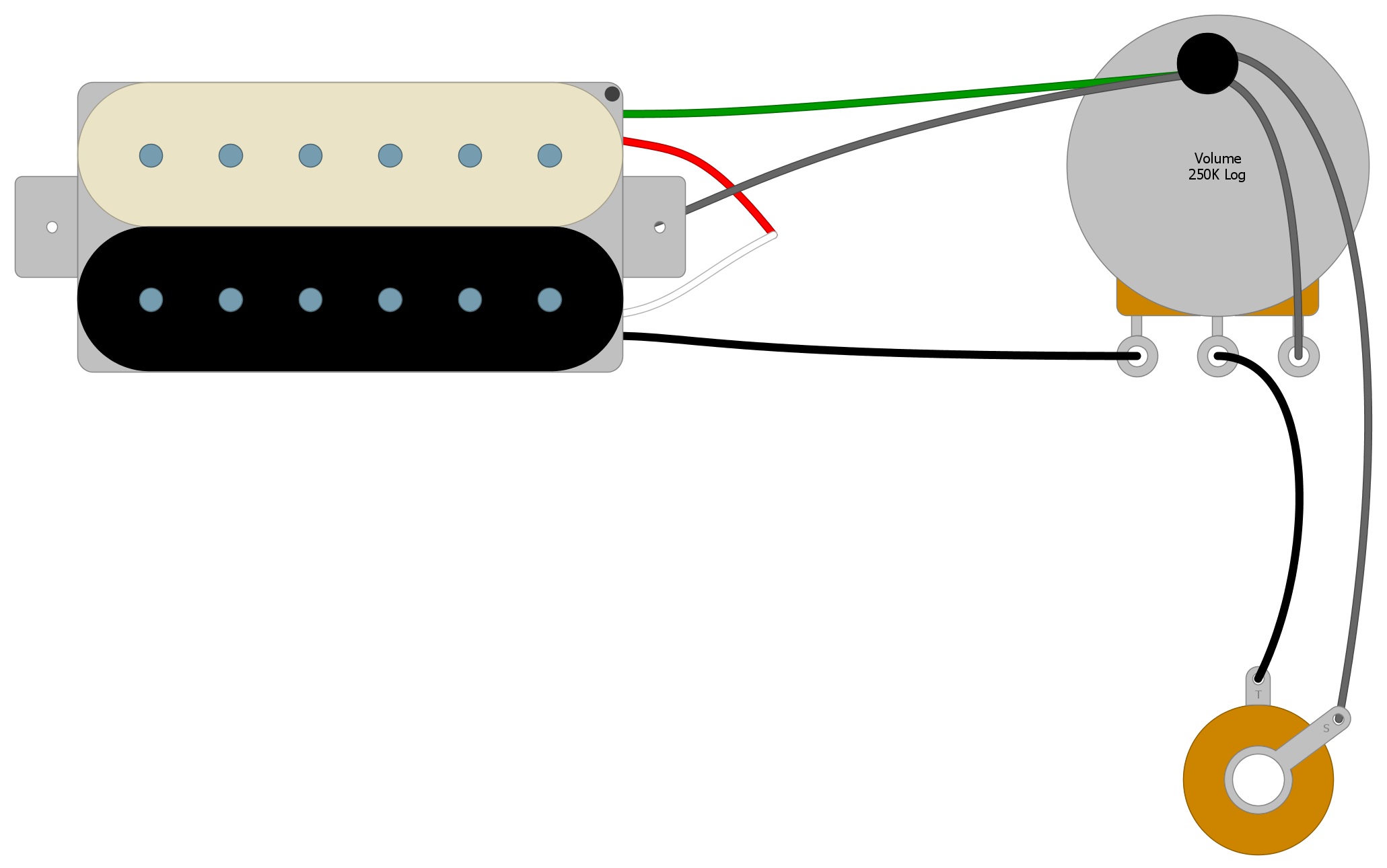
Next, we connect the Volume Control to the Output Jack by running one wire from the center tab of the Volume pot to the Output Jack, and one from the Output Jack to the back of the Volume Control (Fig 5).
Fig 5
Summary
Adding a Tone Control or a Switch will only add more components and will not really change this circuit that much. Look around our website for other ways that you can wire your humbucker and open up your tonal possibilities.
If you’ve enjoyed this article and found it helpful, please feel free to share this with your friends on Facebook and Twitter. For more articles on guitar electronics, visit humbuckersoup.com.