By Ed Malaker
Posted 12/28/2019
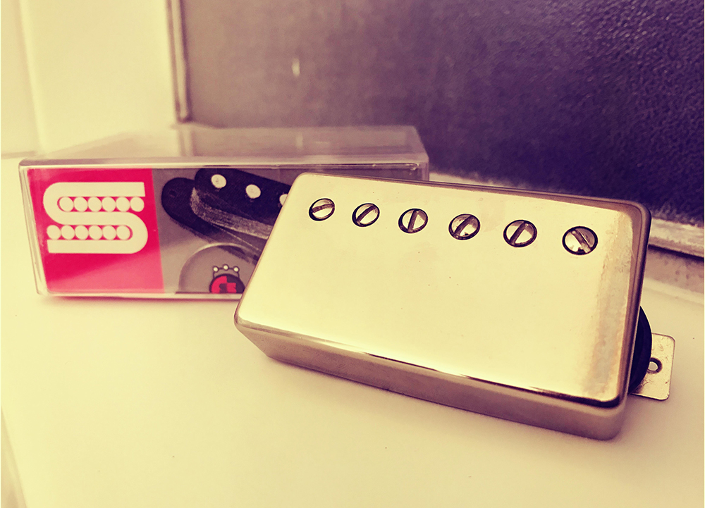
In the Seymour Duncan SH-4 JB wiring that we’ll be doing, the pickup is installed using four colored conductor wires and a bare wire. The SH-4JB is a humbucker that uses a balanced coil configuration to produce improved harmonics with just the right blend of sustain and distortion. It’s a high-output, versatile pickup that sounds very good in the Neck and Bridge positions.
The Wires
The four colored wires are called “conductor” wires because each of them carries current to and from the two coils in the humbucker. Each coil has a positive and a negative wire. The color that goes to each is called the pickup’s “Wiring Code.” Unfortunately, there is no standard Wiring Code, and it varies between manufacturers.
The Bare wire is the Shield. Its primary purpose is to trap radio frequencies that reach the pickup and shuttle them to Ground before they degrade your signal. The Shield and the coils are not connected, but the Shield does connect to Ground.
Wiring Code
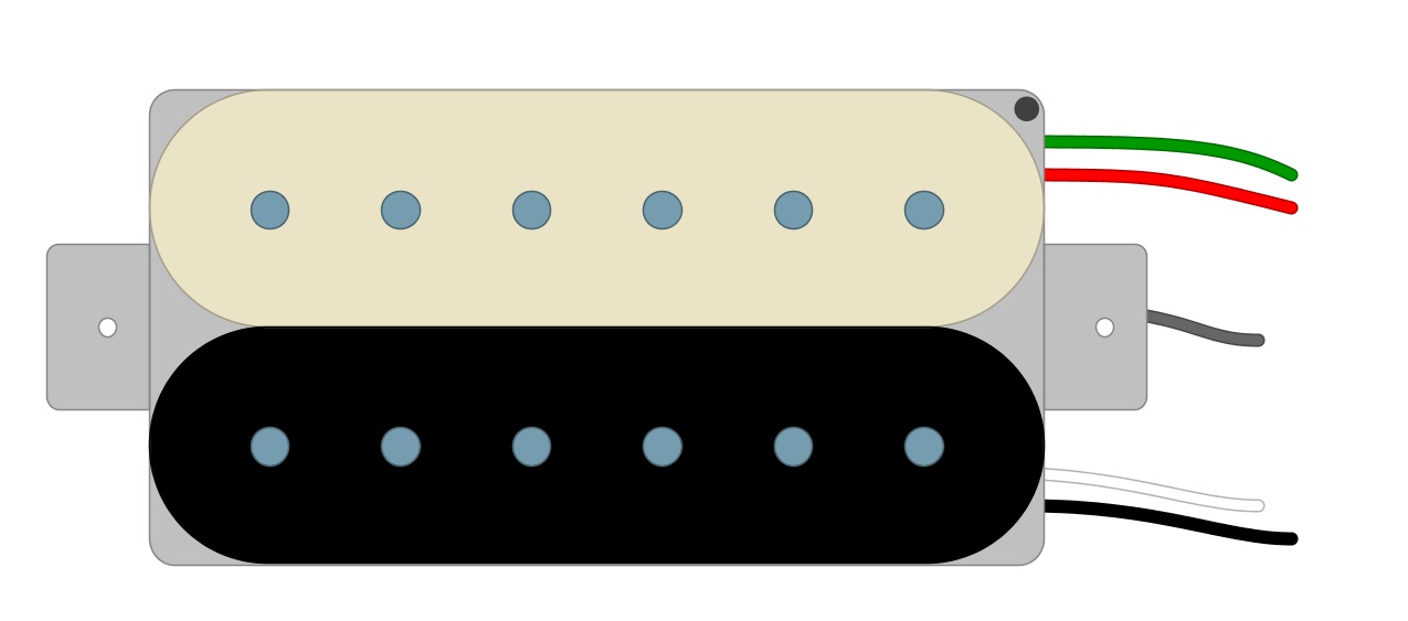
For the Seymour Duncan SH-4 JB, one coil uses Green and Red while the other uses Black and White (Fig 1).
Fig 1
The “standard” way to wire humbuckers is in Series. This means that we run one coil right into the other to create one long continuous path for our signal to travel. Combining the two makes the humbucker almost twice as loud as a single-coil, and it is also responsible for its warmer tones because of phase cancellation.
Installation
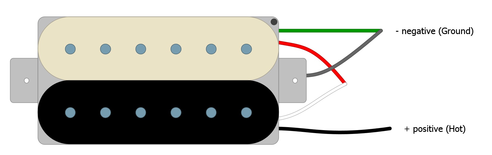
So, we begin our SH-4 JB installation by identifying the Black Wire as the Hot. We solder the Red and White wires together and tape them off. Finally, following standard practice, and using Green as the Ground, we solder the Green and Bare wires together (Fig 2).
Fig 2
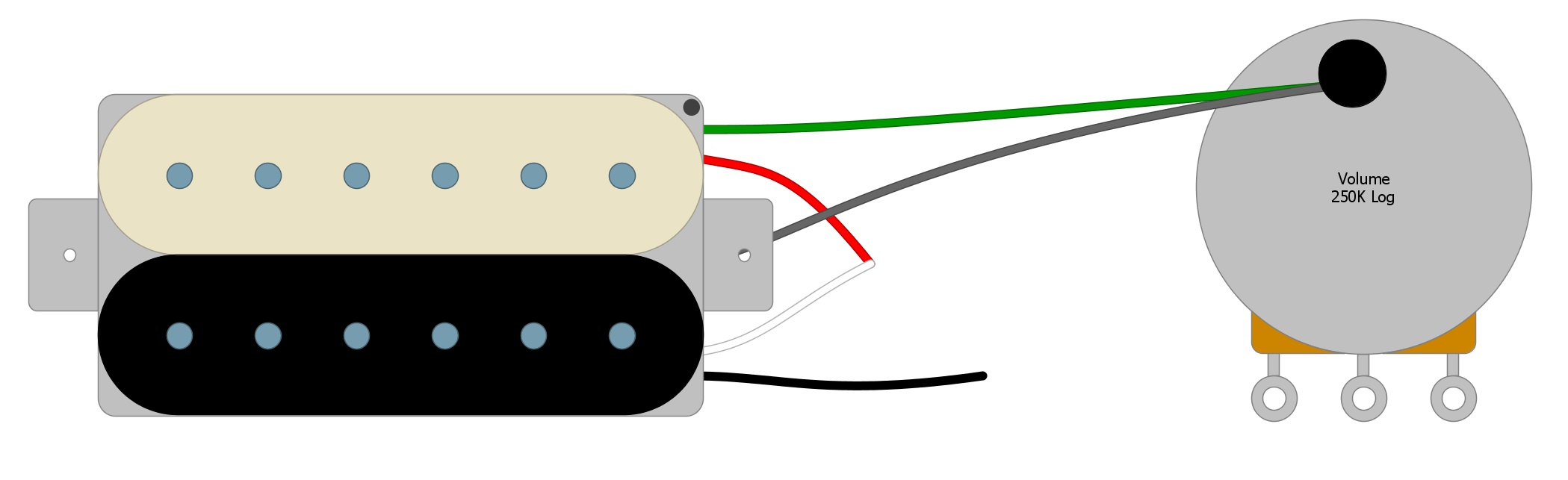
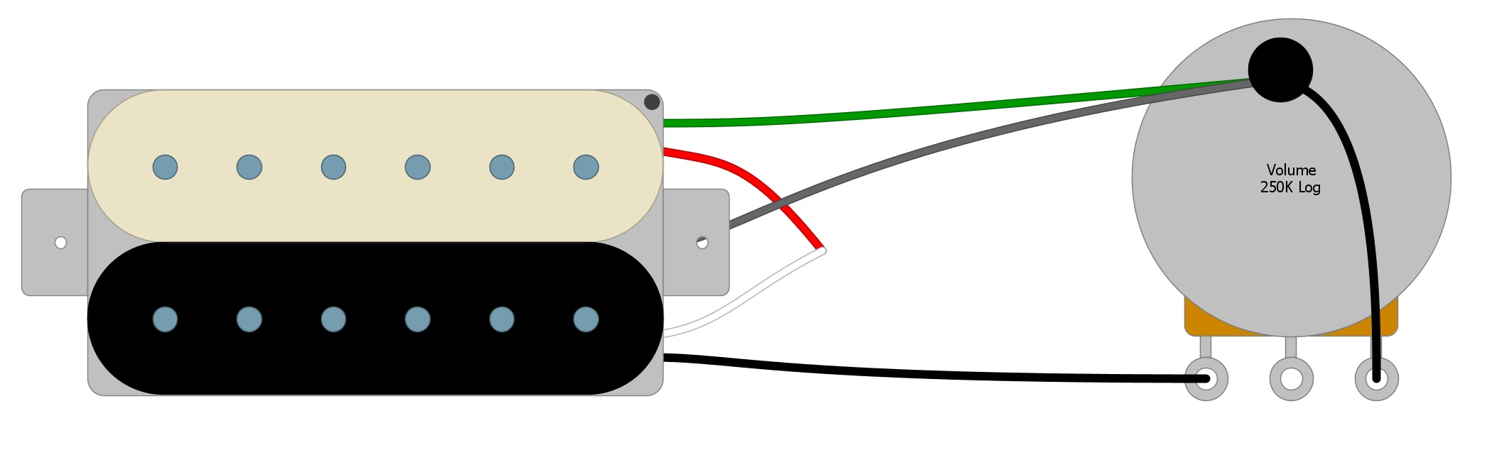
Now we are left with the positive (Black) and negative (Green) wires that we will need to install our pickup. Solder the Green Negative wire and the Bare wire to the back of the Volume pot, which is the standard place to solder all Ground wires (Fig 3).
Fig 3
Next, solder the Black Wire to the first tab on the Volume control. Solder the third tab to the back of the Volume pot, either with a short wire or by physically bending the tab until it contacts the casing of the potentiometer and soldering it in place (Fig 4).
Fig 4
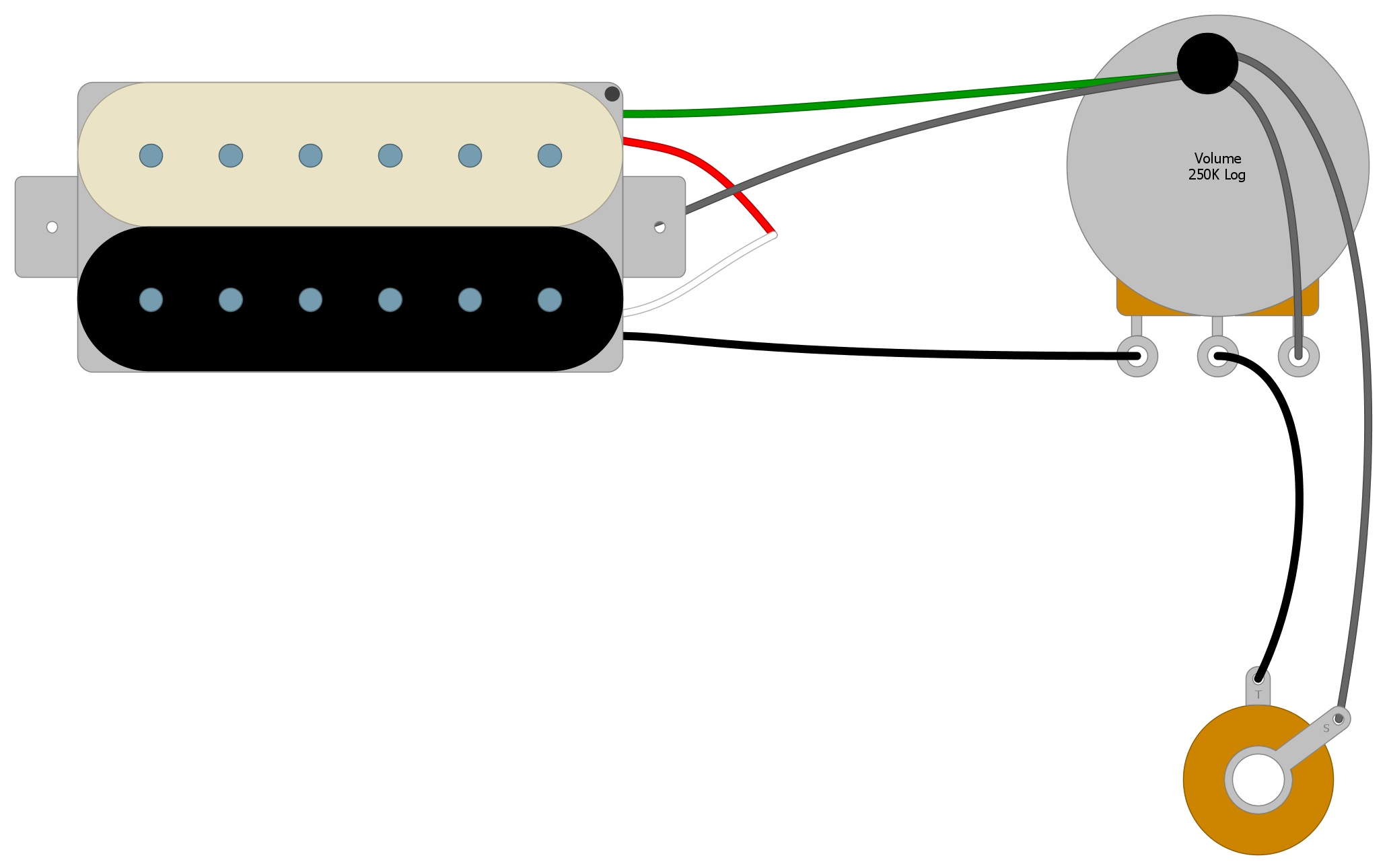
Next, connect one wire from the center tab of the Volume pot to the Output jack, and one from the Output jack to the back of the Volume control (Fig 5).
Fig 5
Project complete!
Summary
This is the most basic way to wire a humbucker pickup, and the key thing to take away is the importance of finding the positive and the negative leads. Adding a Tone Control will only add more components that get soldered to the Volume control. This circuit will not change.
If you have more than one pickup, all of the positive wires will go to the switch. The switch will decide which pickup signal will get sent to the Volume control, and from then on the circuit will be the same as presented here.
If you’ve found this guide helpful, feel free to share this article on Facebook and Twitter. For more articles on guitar electronics, visit humbuckersoup.com.