By Ed Malaker
Posted 06/22/2019
DiMarzio Titan Wiring
The DiMarzio Titan is Jake Bowen’s signature guitar pickup, a humbucker designed to stand out in a three-guitar environment. This humbucker has a lot of emphasis on the midrange frequencies and stays clear under high gain situations. The Titan is a high output pickup that uses a ceramic magnet, and it’s installed using four colored conductor wires and a bare one.
Conductor Wires
One of the first things you might wonder about when you go to install your pickup is why there are so many wires. At first, it might seem confusing, but with a little explanation, it becomes clear.
The Bare wire is the Shield, and many people and many people mistake it for the ground wire. The Shield and the pickup coils are not connected, and its primary purpose is to trap radio frequencies and shuttle them to ground before they penetrate the pickup and enter your signal. The shield wire is always grounded. The remaining four wires lead to the two coils. Each coil has one positive, and one negative, totaling four wires.
Installing Your Pickup
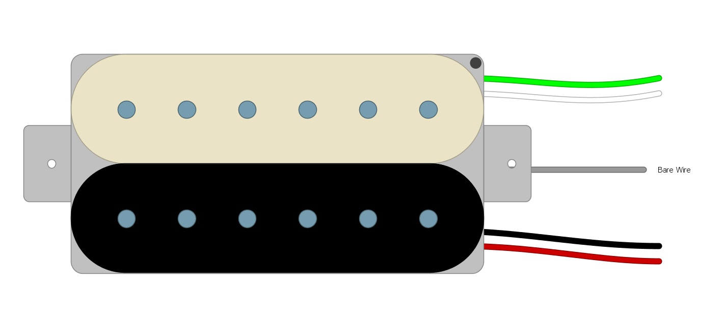
If you were using an unknown humbucker, you would have to test it to find which wires go to each coil because there is no standard. We are going to be concerned with just the Titan, so we can skip that step. For the DiMarzio Titan, one coil uses Red and Black, and the other uses Green and White (Fig 1).
Fig 1
The “Standard” way to wire humbuckers is in Series. Series means that we run one coil right into the other to create one long continuous path for our signal to travel. There are many different ways that we could wire it though. We can wire it in parallel, so it acts more like two single coils, wire it to a switch so we can turn one coil off, and lots of other things. More options are the reason why we have so many wires. For now, we will do it the Standard way.
To wire our pickup the standard way we begin by considering the Red Wire to be the Hot Wire. We solder the Black and White wires together and tape them off, and we use the Green Wire as the Ground Wire. It’s standard practice to solder the Green and Bare wire together (Fig 2).
Fig 2
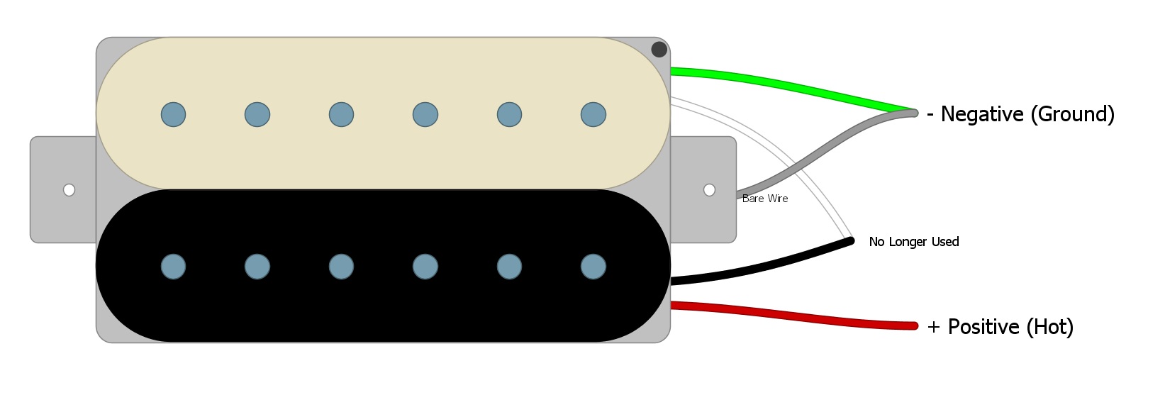
Now we are left with the positive (Red) and negative (Green) wires that we will need for installing our pickup into the guitar.
Wiring to the Volume Control
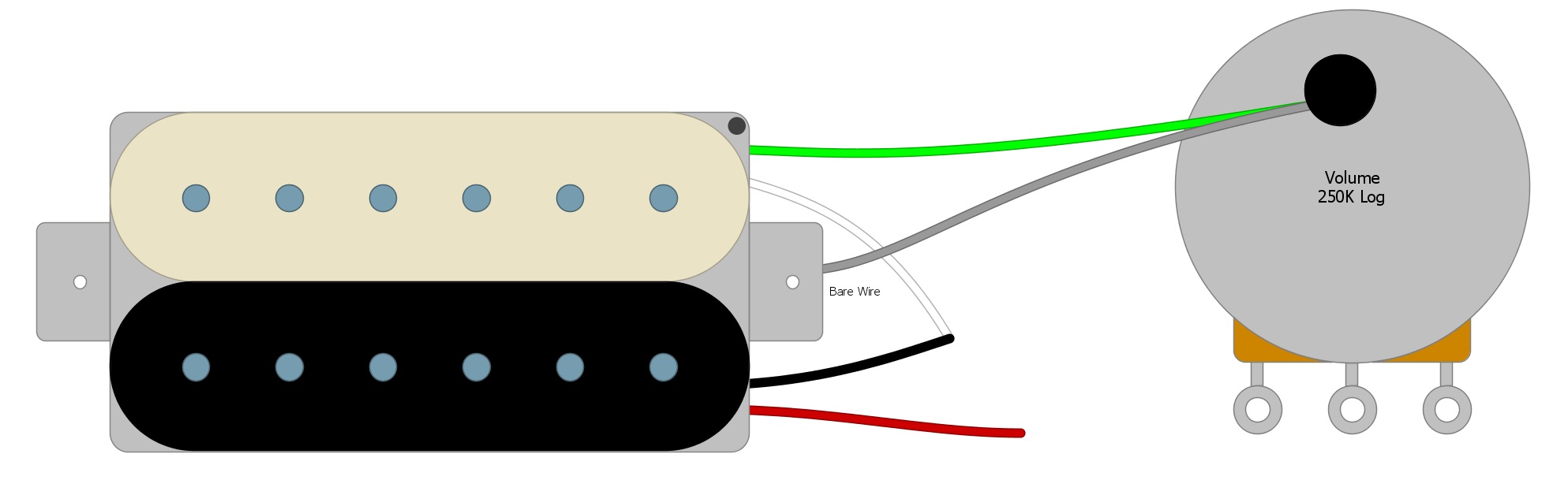
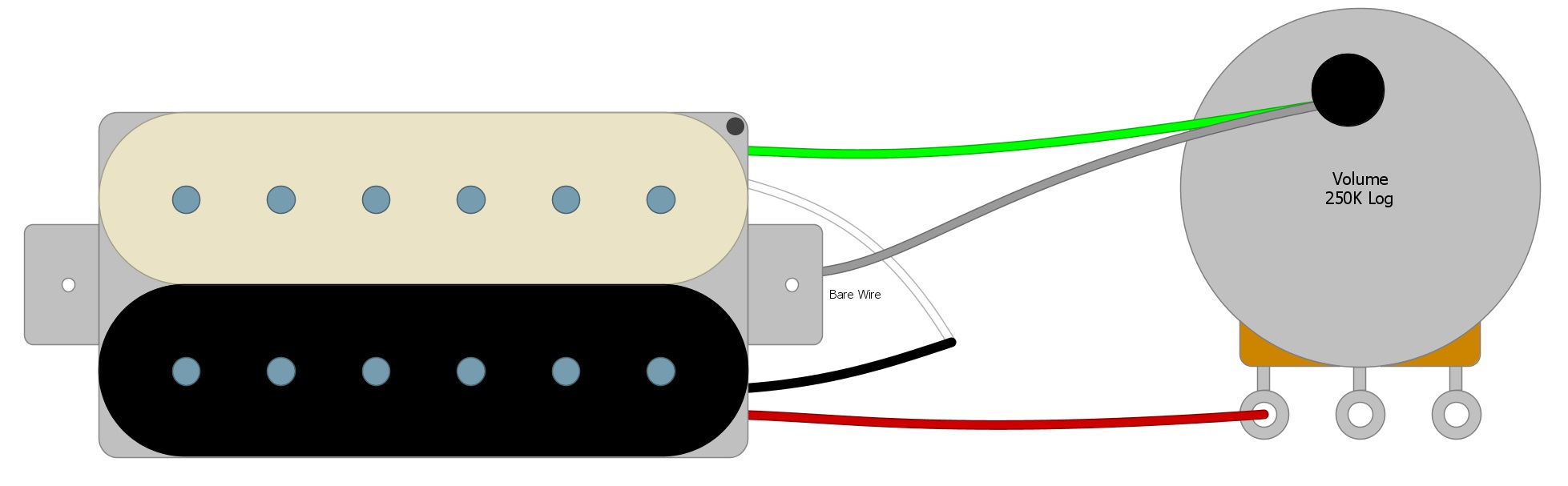
First, we’ll solder the Green Negative wire and the Bare wire to the back of the Volume Pot which provides ample space to solder our ground wires for all of our pickups (Fig 3).
Fig 3
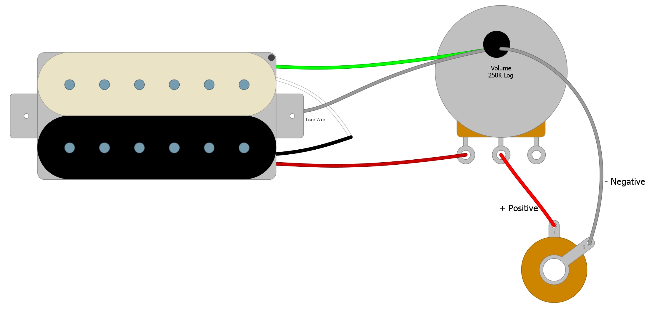
Next, we’ll solder the Red Wire to the first tab on the Volume control. It is also ubiquitous to solder the third tab to Ground (the back of the Volume pot), either with a short wire or by bending the tab until it contacts the back of the potentiometer and soldering it in place (Fig 4).
Fig 4
Next, we connect the Volume Control to the Output Jack with two wires, and we are finished (Fig 5).
Fig 5
Summary
Adding a Tone Control or a Switch will only add to this circuit, and you can find this circuit hidden in almost any humbucker setup. Look around humbuckersoup.com for other ways that you can wire your humbucker and open up your tonal possibilities.
If you’ve found this article helpful, please feel free to share this with your friends on Facebook and Twitter.