By Matthew Moehlenkamp
Posted 06/12/2025
Many believe that the Holy Grail of guitar tone only comes from a tube guitar amplifier. There is something special about how tubes react to a player’s style and choice of guitar. They can go from a sparkling clean to all-out metal mayhem. In this article we will take a look at the components of a tube preamp and how changes to them affect the gain and tone.
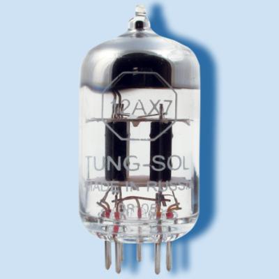
The Preamp Tube
The main purpose of the preamp tube is to amplify the signal from the guitar to a high enough level to drive the power tube. When you combine high gain with multiple gain stages, you can create varying degrees of clipping, from subtle crunch to full-on metal distortion. The most popular preamp tube is by far the 12AX7. It can be found in different versions with varying amounts of gain and frequency response. Just changing the brand of the tube can have a substantial effect on the tone of the amp. Through the use of a socket adapter, some 8-pin octal preamp tubes such as the 6SL7 can be substituted into a preamp circuit and totally change the character of the amp. The common cathode circuit is the most common for the gain stages in a tube preamp.
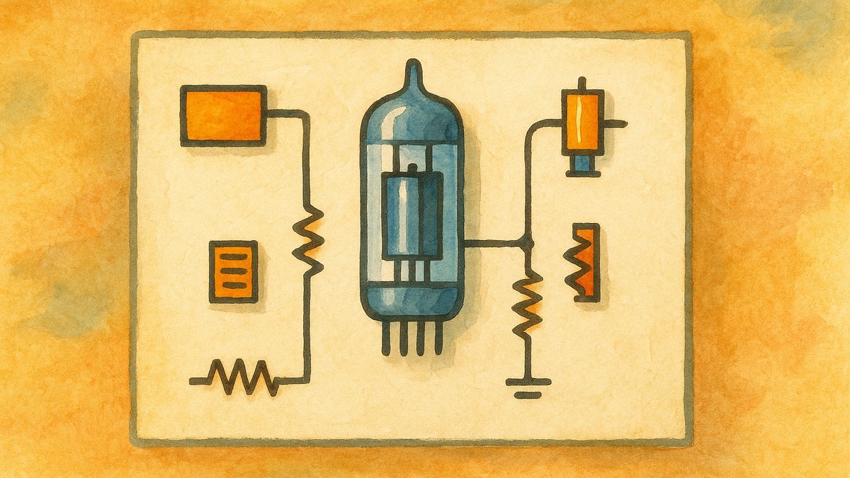
What Components Make Up a Common Cathode Tube Preamp Circuit
The figure below shows the basic components of a tube preamp gain stage (common cathode).
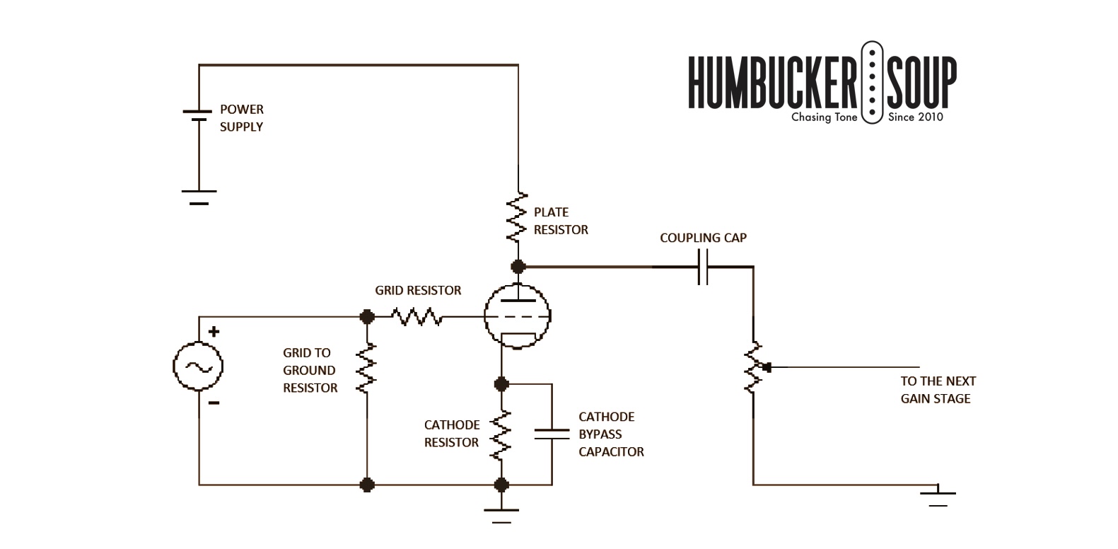
The Power Supply
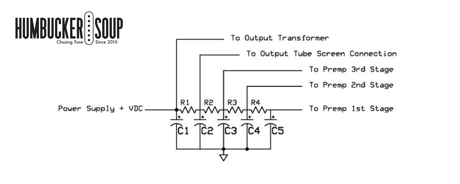
The power supply for a tube guitar preamp will normally run in the 250 VDC to 300 VDC range when 12AX7 tubes are used. The supply will be well-filtered and located after the power amp supply. The supply will cascade down from the power section to the last preamp tube and on down through all tubes to the first. The first tube will be fed with the lowest voltage, with an RC network separating the power to each stage.
The Grid to Ground Resistor
The grid-to-ground resistor is placed after the input, before the grid resistor. A typical value is 1M for the first stage. It is used to give the grid a reference to ground. In the following gain stages, there will not be a grid-to-ground resistor if there is a potentiometer, such as a gain control. In other stages, it will form half of a voltage divider, providing signal reduction and a ground reference to the next tube. A typical value in these stages is 470K.
The Grid Resistor
The grid resistor should be connected directly to the grid pin of the preamp tube. It should be located as close to the pin as possible or soldered directly to it. It is used to filter out high-frequency interference or noise. It is a must-have on the first gain stage after the input as it serves to filter out radio frequencies and other noises. It also prevents oscillations. In the first stage, typical values can be 33K to 100K. There is no real loss of signal level with increased values, just attenuated higher frequencies. In the following gain stages, the values can range from no grid resistor to 470K. A higher value can be used to tame the harshness of a high-gain amp and roll off some of the high-end buzz.
The Plate Resistor
The plate resistor is connected between the DC power supply and the plate of the preamp tube. Common values for the plate resistor for a 12AX7 tube are between 100K and 220K. The larger value will have more gain, but it’s not a very big difference. The value will affect the bias point of the stage and the DC voltage at the plate. When the DC voltage is closer to half of the supply voltage, the stage will have more clean gain, and when it does clip the signal, it is more symmetrical, clipping both the positive and the negative swing.
The Cathode Resistor
The cathode resistor is connected between the cathode of the preamp tube and ground. Values of a typical gain stage will range from 820 to 2.2K. Higher values such as 10K up to 39K are used by some manufacturers to get asymmetrical clipping of the signal.
The Cathode Bypass Capacitor
The cathode bypass capacitor is connected in parallel with the cathode resistor, between the cathode of the tube and ground. It is used to increase the audio signal gain without affecting the bias point. Its values can range from .68uF up to 25uF. It is commonly used with cathode resistor values of 1.5K to 2.2K. A lot of amps will only have this capacitor in the first gain stage. Smaller values are used to boost the higher frequencies, while larger values will boost the entire signal.
The Coupling Capacitor
The coupling capacitor is connected to the junction of the plate resistor and the plate of the preamp tube. It carries the audio signal on to the next stage. The capacitor has to be used here to block the DC voltage from the previous stage from entering the next stage. Typical values are .022uF and .047uF. You will see smaller values such as .01uF in some designs. Smaller values will roll off some of the bottom end and can increase the top end.
Summary
This is a basic overview of the common cathode circuit that is used for the gain stages in a tube preamp. In my future articles, we will explore the other circuits that make up a complete tube preamp and look at how component values affect the output signal.
I hope you enjoyed reading this overview. Please come back for my future articles and take a look at the other content on humbuckersoup.com
Matt